background image

January 2001

3 - 8

Trouble Shooting, Error Codes and Fault Diagnosis

Service Manual Cafitesse 500

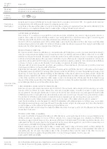
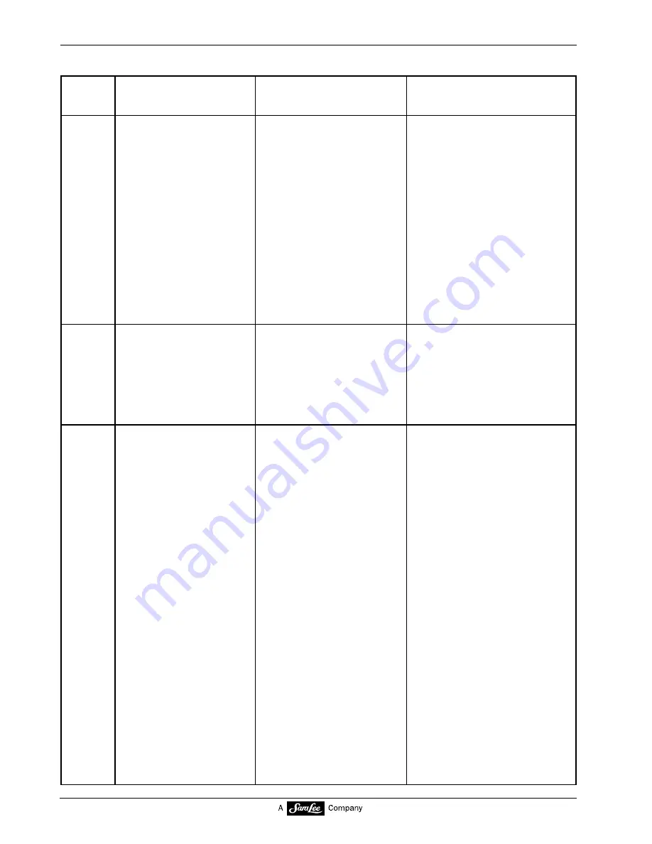
Display

Malfunction

Cause

Remedy

1. Check  the  wires,  replace

them  if  necessary.

2. Replace  the  board  of  the

service  panel
(see  pg.  5.K-8)

3. Replace  the  interconnection

board  (see  pg.  5K-9)

  4. Replace  control  board  box

(see  pg.  5K-4)

Reset  program  to  factory
default  and  reprogram

1. Clean  combi-trough  and

replace  it  if  required
(see  pg. 5.C-7)

2. Check  motor  and  wires

(BU21),  replace  them  if
necessary  (see  pg.  5.C-5)

3. Replace  the  sensor  board  or

check  the  wires  (BU  23)
(see  pg. 5.C-6)
Replace  control  board  box  if
necessary.

1. Wires  PIN  13-16  (BU21-

I

2

C)  between  control

board  box  and  inter-
connection  board  are
defective

2. Board  of  the  service

panel  is  defective.

3. Interconnection  board

defective

  4. MCB  or  I

2

C  bus  driver

board  defective

Coin  module  not  used  in
the  U.S.

1. Auto-diaphragm  moves

sluggishly

2. Motor  for  auto-diaphragm

or  wires  P18/2,4  (BU  21)
defective

3. Sensor  board  (2  Hall

sensors)  or  wires  P18/5-
7,  P20/3,4  (BU23)
defective

ERR13

Error  in  internal
communication.
"ON/OFF"  LED  flashes.
Dispenser  remains  on.
Cooling  remains  on.

ERR14

Error  in  Coin  Interface
The  LEDs  for  "EMPTY"
and  "ON/OFF"  are
flashing.
Dispenser  is  switched  off.
Cooling  remains  on.

ERR15

Error  auto-diaphragm
The  LEDs  for  "EMPTY"
and  "ON/OFF"  are
flashing.
Dispenser  is  switched  off.
Cooling  remains  on.
Movement  of  auto-
diaphragm  incorrect.
Nominal  position  was  not
reached  after  3  tries.

Summary of Contents for CAFITESSE 014

Page 1: ...CAFITESSE 500 014 SERVICE MANUAL coffee coffee coffee coffee coffee coffee stop BREWING hot water www coffeefast com ...

Page 2: ...nded for internal use only Douwe Egberts Coffee Systems issues no explanation or guarantees with regard to the contents of this publication and expressly disclaims all responsibility for any implied guarantees Douwe Egberts Coffee Systems reserves the right to revise and change the contents of this manual without notice Published by Douwe Egberts Coffee Systems January 2001 2001 Douwe Egberts Coff...

Page 3: ... This Service Manual is valid for machines of the type CFT014 Cafitesse 500 A2 January 2001 Service Manual Cafitesse 500 ...

Page 4: ......

Page 5: ...s 3 and Fault Diagnosis Programming 4 Functions 5 Water System A Brewing System B Dosing System C Product Delivery D Cooling System F Housing G Power Supply and Control System K External Options L Payment Systems P Preventive Maintenance 6 Service Procedures 7 Service Information 8 Modification Instructions 9 Spare Parts List 10 ...

Page 6: ...nstructions Service Manual Cafitesse 500 1 Preface and Safety Instructions Contents 1 1 Preface How to use the manual 2 1 1 1 General 2 1 1 2 Structure of the Manual 3 1 1 3 Definition of Options and Accessories 4 1 2 Safety Instructions 5 ...

Page 7: ...Preface How to use the Manual 1 1 1 General This service manual is intended for trained service technicians who have attended the training courses for this dispenser This service manual is not to teach technical details about this dispenser but it can be considered and used as a reference book for trained technicians ...

Page 8: ... in this system interact 4 Electrical diagrams This paragraph describes the electrical input and ouput of the water system 5 Technical specifications This paragraph explains technical specifications of the water system 6 Options Available options especially for the water system 7 Accessories Accessories for the water system 1 1 2 Structure of the Manual Chapter The service manual is divided into 1...

Page 9: ... is subject to changes consecutively numbered Service Information sheets will inform you on these changes These are to be filed in chapter 8 in the Service Manual Changes that must be carried out for existing dispensers will be announced by Modification Instructions These are to be filed as chapter 9 in the Service Manual After the modifications have been carried out the corresponding number must ...

Page 10: ...ble or a counter The dispenser can be used to deliver hot beverages such as coffee decaffeinated coffee or milk containing beverages e g cappuccino café au lait or milk Additionally hot water can be delivered The present dispenser can only be used for liquid beverage concentrate in single use flexi packs The manufacturer can not be held responsible for dispensers that were used for purposes other ...

Page 11: ...nd to the electric power supply in accordance with the local regulations WARNING The dispenser must be connected to a properly fused electric circuit We recommend the connection to a supply with a ground fault current safety switch The connection must be made using a plug and socket grounded according to regulations Observe the local regulations WARNING If the dispenser is not used for a longer pe...

Page 12: ...be refilled CAUTION Do not switch off the dispenser between beverage deliveries in order to keep the optimum water temperature in the boiler CAUTION Clean the inside and outside of the dispenser by using a damp cloth and do not splash it To clean the dispenser only use cleaning agents approved by the food industry Never use high pressure sprays for cleaning CAUTION The use of the special Cafitesse...

Page 13: ...nstructions Service Manual Cafitesse 500 1 Preface and Safety Instructions Contents 1 1 Preface How to use the manual 2 1 1 1 General 2 1 1 2 Structure of the Manual 3 1 1 3 Definition of Options and Accessories 4 1 2 Safety Instructions 5 ...

Page 14: ...Preface How to use the Manual 1 1 1 General This service manual is intended for trained service technicians who have attended the training courses for this dispenser This service manual is not to teach technical details about this dispenser but it can be considered and used as a reference book for trained technicians ...

Page 15: ... in this system interact 4 Electrical diagrams This paragraph describes the electrical input and ouput of the water system 5 Technical specifications This paragraph explains technical specifications of the water system 6 Options Available options especially for the water system 7 Accessories Accessories for the water system 1 1 2 Structure of the Manual Chapter The service manual is divided into 1...

Page 16: ... is subject to changes consecutively numbered Service Information sheets will inform you on these changes These are to be filed in chapter 8 in the Service Manual Changes that must be carried out for existing dispensers will be announced by Modification Instructions These are to be filed as chapter 9 in the Service Manual After the modifications have been carried out the corresponding number must ...

Page 17: ...ble or a counter The dispenser can be used to deliver hot beverages such as coffee decaffeinated coffee or milk containing beverages e g cappuccino café au lait or milk Additionally hot water can be delivered The present dispenser can only be used for liquid beverage concentrate in single use flexi packs The manufacturer can not be held responsible for dispensers that were used for purposes other ...

Page 18: ...nd to the electric power supply in accordance with the local regulations WARNING The dispenser must be connected to a properly fused electric circuit We recommend the connection to a supply with a ground fault current safety switch The connection must be made using a plug and socket grounded according to regulations Observe the local regulations WARNING If the dispenser is not used for a longer pe...

Page 19: ...be refilled CAUTION Do not switch off the dispenser between beverage deliveries in order to keep the optimum water temperature in the boiler CAUTION Clean the inside and outside of the dispenser by using a damp cloth and do not splash it To clean the dispenser only use cleaning agents approved by the food industry Never use high pressure sprays for cleaning CAUTION The use of the special Cafitesse...

Page 20: ...quirements 7 2 2 5 External Options 8 2 3 Unpacking 9 2 3 1 Unpacking the Dispenser 9 2 3 2 List of all Items that are supplied with the Dispenser 9 2 3 3 Disposal of Packaging and Dispenser at the End of their Service Life 10 2 4 Installation Putting into Operation 10 2 5 Checklist Instructions for the Customer 20 2 6 Transfer of the Dispenser to the Customer 21 incl HACCP Hazard and Critical Con...

Page 21: ... 5 in 395 mm Depth 24 6 in 625 mm Shipping weight 89 6 lbs Transport in general CAUTION Transport the dispenser carefully Do not throw the dispenser or handle it incorrectly Do not transport several unfastened dispensers on top of each other Only transport the dispenser in upright position When storing the dispenser ensure that it is only stored indoors and take precautions against parasites Prote...

Page 22: ... hot water Pack the dispenser in such a manner that a safe transport is guaranteed Use the original packaging if possible Fig 1 2 Before storing the dispenser for a longer time period it must be cleaned correctly When used dispensers are stored intermediately for a long time the inlet valve of the water supply hose towards the boiler must be disconnected in order to ensure that the hose is empty I...

Page 23: ...nts 2 2 1 Tools The following tools are required for installation Tool required for 1 Service device Programming 2 Pressure gauge Measuring the water pressure 3 Several e g screw drivers for installing customer specific kits 4 Rotary switch Adjusting the heating capacity C L R R e p C o d e C l o c k I n p u t s e r v i c e d e v i c e ...

Page 24: ... pressure max 140 psi Dispenser Connections for hoses 3 8 o d flare Connecting pieces are included The dispenser must be installed with adequate back flow protection that complies with local regulations 2 2 2 Water Supply CAUTION Check the drinking water quality before the installation A water filter must always be installed CAUTION When using new water pipes flush them sufficiently before the ins...

Page 25: ...ectly fused electric circuit Connection to a supply with a ground fault current safety switch is recommended The connection must be made using a plug and socket grounded and sized according to local regulations Voltage Tank Wattage Total Wattage Actual Amps Breaker Size 120 1600 1800 15 20 208 240 2200 2900 2400 3100 11 5 12 9 20 20 208 240 2700 3600 2900 3800 13 9 15 8 20 20 208 240 4200 5600 440...

Page 26: ...g compartment lid is open Plan view 2 2 4 Space Requirements 30 7 in 1 9 in 20 2 in 12 59 in Minimum requirements for floor walls and ceilings in the area of the dispenser Floor Level nonskid floor Walls There are no particular requirements for walls since the dispenser is not designed for wall mounting Ceiling Dustfree clean 20 2 in 41 2 in Flexi Pack 9 84 in 10 98 in 29 7 in ...

Page 27: ...January 2001 2 8 Installation Putting into Operation Service Manual Cafitesse 500 2 2 5 External Options to be used by Opcos and distributors for national information e g on external filters ...

Page 28: ...ts kit Coffee pots Water filter and check valve Dishwasher exchange kit 2 3 Unpacking 2 3 1 Unpacking the Dispenser Remove the banding from the cardboard box carefully Do not use sharp objects or cut the carton to avoid scratching the dispenser Remove the upper half of the box by lifting straight up Remove the top and side packing cardboard Pull the dispenser with the plastic bag out of the cardbo...

Page 29: ...ary Measure the water pressure All electrical and plumbing connections must be according to national and local codes and regulations If you are unsure of these codes enlist the assistance of a qualified electrician or plumber Used packaging Packaging Material Outer cardboard box Cardboard Inner packaging Corrugated board Disposal of material must always be done in accordance with national legal sa...

Page 30: ...SSELINHALT BOILER CAP CAPACIT DE LA BUILLOIRE bar 208 240 2 9 3 8 2 7 3 6 20 E I N G E S T E L L T E W E R T E S E L E C T E D V A L U E S V A L E U R S S L E C T I O N N E S U 2 IPX1 LISTED 28G0 C Fig 1 Legend of the rating plate example Fig 1 1 Machine type 2 Machine number 3 6 Electric connection values 7 Water pressure range 8 Approval agencies 9 Sticker for adjusted values must be adhered acc...

Page 31: ...measuring gauge which is available locally Fig 2 Pressure should be checked under the most unfavorable conditions e g when all remaining water consuming locations are opened dynamic and when all are closed static Connect the pressure gauge to the water pipe with a pressure hose It is possible to use the hose which serves for connecting the dispenser later CAUTION The pressure gauge must be install...

Page 32: ...flat horizontal counter table base stand or a table at a wall At the back side of the dispenser a minimum of 2 in is necessary to ensure sufficient cooling It is recommended to mount a wall spacer to provide this clearance see pg 5 G 9 Place the dispenser on the table Power supply cable The dispenser is delivered as a standard with a power supply cable for 250 V 30 A Replace the power supply cable...

Page 33: ...e drip grid 1 Fig 1 Remove the small dummy cap 3 Fig 2 Position the rotary switch 4 service tool for switching the heating Fig 3 Adjust the heating according to the previously selected configuration see Technical Data CAUTION The heating capacity must only be switched over when the dispenser is disconnected from the mains supply Trained service technicians only may switch over the heating capacity...

Page 34: ...on request U4 S 2 2 kW 2 9 kW 20 A 20 A U5 R S T 6 6 kW 8 7 kW parallel 50 A 50 A U6 S T parallel 1 6 kW 20 A Adjustment of the heating capacity with the rotary switch service tool right heating element T 16 03 Ohm 10 left heating element S 19 96 Ohm 10 central heating element R 25 80 Ohm 10 1 TYPE CFT XX4 TYPE CFT XX4 MAINS VOLTAGE MAINS FUSE HEATING POWER HEATING POWER MAINS FUSE MAINS VOLTAGE 2...

Page 35: ... 4 5 8 4 2 5 6 30 EINGESTELLTE WERTE SELECTED VALUES VALEURS SÉLECTIONNÉES U1 208 240 2 4 3 1 2 2 2 9 20 EINGESTELLTE WERTE SELECTED VALUES VALEURS SÉLECTIONNÉES U4 120 1 8 1 6 20 EINGESTELLTE WERTE SELECTED VALUES VALEURS SÉLECTIONNÉES U6 208 240 6 8 8 9 6 6 8 7 50 EINGESTELLTE WERTE SELECTED VALUES VALEURS SÉLECTIONNÉES U5 Fig 4 1 9 2 3 4 5 6 8 7 Rating plate CFT 014 CFT 500 AX UL 0 without whip...

Page 36: ... the push button cover 1 press it slightly Fig 5 Install the rest of the buttons per the end users requested drink selection With those buttons that shall not actuate a delivery insert the flat black dummy button Fig 6 Connecting the dispenser coffee coffee coffee coffee stop hot water BREWING coffee coffee coffee coffee coffee coffee stop hot water BREWING coffee 1 Fig 5 Fig 6 ...

Page 37: ... holder Remove the plastic panel Remove the protective film from the panel Place the advertising photo behind the plastic panel and re insert the plastic panel If necessary place the advertising photo on the back of the dispenser see pg 5 G 8 Insert the flexi packs Program the dispenser according to the requirements of the customer see chap 4 Remove any grease from the corresponding area on the ba...

Page 38: ... Code 8 will be displayed The fault indication will be displayed until the cooling compartment has the correct temperature This can last approx several hours If the dispenser has been out of operation for a very long time always place a collecting vessel underneath the hot water outlet actuate the hot water delivery button 2 and drain at least 2 5 gal of hot water Fig 12 When the dispenser is in n...

Page 39: ...January 2001 2 20 Installation Putting into Operation Service Manual Cafitesse 500 2 5 Checklist Instructions for the Customer ...

Page 40: ...January 2001 2 21 Installation Putting into Operation Service Manual Cafitesse 500 2 6 Transfer of the Dispenser to the Customer incl HACCP Hazard and Critical Control Points ...

Page 41: ...r inlet temp max 167 F Dynamic pressure min 11 psi with 2 64 US gal min Static pressure max 140 psi Cold water connection Dynamic pressure min 11 psi for Café Cool optional 0 32 US gal min Static pressure max 101 5 psi Water filling capacity 2 64 US gal atmospheric boiler Concentrate capacity coffee or milk pack containing 2 liters 0 53 US gal each Electrical connection load For the connected load...

Page 42: ...witch The dispenser is equipped with 2 relays Power supply cable 3x10AWG 30 A Length of power supply cable approx 5 9 ft Boiler Open system capacity 2 64 US gal electronic control of the water temperature dry running protection electronic monitoring by means of a float and a temperature limiter for the heating element electronic low temperature indicator electronic boil over sensor Beverage delive...

Page 43: ...istance to wall 2 in measuring from the back side of the dispenser The dispenser is protected from dripping water Heating capacities The dispenser is equipped with a heating capacity changeover switch which is used to connect it to all of the commonly used main voltages main fuses see table page 2 15 CAUTION Disconnect the dispenser from the mains before changing the heating capacity There is a da...

Page 44: ... on temp boiler temperature is less than 141 8 F Switching off temp boiler temperature equals programmed temperature 7 2 F Disconnecting the heating via relay Boiler temperature is greater than programmed temperature Interrupting the safety circuit by means of Boiler temperature is greater than programmed a watchdog relay temperature 9 F ERR 4 switching off by software Boiler temperature is greate...

Page 45: ...the cup carrier Material stainless steel Cup stop Material PC Drip tray Material PC Drip grid Material stainless steel Splash panel Material stainless steel Button Material acrylnitrile butadiene styrole polymer Cup carrier rod Material PC Height adjustment of the cup carrier Material acrylnitrile butadiene styrole polymer Guiding pipes Material stainless steel Temperature sensor Connecting temper...

Page 46: ...using front part Material stainless steel powder coating Coating RAL 9005 Cover Material plexiglass Operating panel Material ABS Control unit operating panel Operating voltage 24 V 5V Peltier circuit Operating voltage 13 5 V Fuse power supplies Switched mode power supply 4 AT Control unit 3x5 AT ...

Page 47: ...uary 2001 3 1 Trouble Shooting Error Codes and Fault Diagnosis Service Manual Cafitesse 500 3 Trouble Shooting Error Codes and Fault Diagnosis Contents 3 1 Fault Diagnosis 2 3 2 Error Codes 3 3 3 Notes 13 ...

Page 48: ...ackgrounds 2 Are the error codes displayed on the see 3 2 see 3 2 or dispenser Which codes perform step 3 3 Is the problem described in 3 3 proceed as perform step 4 described in 3 3 4 Is the current supply okay perform step 5 see 3 2 5 Is the DC supply okay perform step 6 see 3 2 6 Is the water supply okay perform step 7 see 3 2 7 Are the flexi packs inserted correctly see 3 2 see 3 2 and full ...

Page 49: ...n the Service Panel ERR 11 Start the programming mode with the service device and quit Reprogram if necessary ERR 3 4 5 15 16 18 19 20 21 and 23 Can be reset by actuating the ON OFF button Priorities of the Errors high low ERR 16 ERR 10 11 23 22 15 2 4 3 5 17 7 6 14 CLEAN FLUSH SANIT 18 19 20 21 CODE 8 ERR 9 Apart from the indicated causes a defective electronic control system could also be the re...

Page 50: ... it or correct its position 1 Check volume 2 Check the wires see pg 5 K 18 19 from heating capacity change over switch to heating Replace the control board box if necessary 3 Replace the relay cable harness to control board box and BU23 check contactor 4 Replace boiler cover see pg 5 A 7 1 Let the boiler cool down 2 Replace relay on the power supply unit see pg 5K 6 3 Decalcify or replace the temp...

Page 51: ...Y and ON OFF are flashing The dispenser is switched off The cooling system remains on Exception After switching on the time period for Time out is 2 min As soon as the boiler has been filled the time period for Time out is again 30 sec ERR6 Peltier current too high I is greater than 6 A The LEDs for EMPTY and ON OFF are flashing The dispenser remains operative Cooling is switched off 1 Replace the...

Page 52: ...ing is switched off CODE 8 Cooling compartment temperature is higher than 44 6 F ON OFF LED flashes Cooling is switched on Dispenser remains on The error is automatically reset when the cooling compartment temperature drops below 42 8 F 1 Clean heat sink 2 Clean air filter see pg 6 3 3 Check distance to wall min 2 inches Check whether the air flow is sufficient 4 Replace fan see pg 5 F 2 5 Replace...

Page 53: ...hed off Cooling remains on 1 Ambient temperature too low less than 33 8 F 2 The wires P12 from the control board to the sensor is defective 3 Temperature sensor is defective 4 Pack with frozen coffee concentrate 1 Control error storage malfunction 1 Incorrect values or error in the EEPROM 1 Control board defective Display Malfunction Cause Remedy 1 The error is automatically reset when the tempera...

Page 54: ...3 16 BU21 I2 C between control board box and inter connection board are defective 2 Board of the service panel is defective 3 Interconnection board defective 4 MCB or I2 C bus driver board defective Coin module not used in the U S 1 Auto diaphragm moves sluggishly 2 Motor for auto diaphragm or wires P18 2 4 BU 21 defective 3 Sensor board 2 Hall sensors or wires P18 5 7 P20 3 4 BU23 defective ERR13...

Page 55: ...ctive mixer remains off Display Error Cause Remedy 1 The water in the boiler has boiled Boil over protection was triggered 2 Float is stuck in upper position Dry running protection was triggered 3 Fuses wiresP04inthe24 V circuit defective 4 Switching mode console defective 1 Optical sensor float in the boiler or wires P02 11 13 BU24 defective 2 Solenoid valve inlet or outlet or wires P02 1 6 BU 24...

Page 56: ...Y and ON OFF are flashing The dispenser remains on The delivery of all products for which the right mixer motor is used is blocked All products for which the rightmixermotorisnotused can be delivered Cooling remains on During the FLUSH procedure the defective mixer remains off Display Error Cause Remedy 1 Mixer motor moves sluggishly 2 Mixer dirty 3 Plug defective P06 4 Motor defective 1 Motor def...

Page 57: ...water have been refilled 1 Combi trough not properly installed 2 Sensor board 2 Hall sensors defective or circuit interrupted wires P18 5 7 P20 3 4 BU23 1 CLEAN is displayed 4 hours before FLUSH time ERR21 Rright mixer motorcurrent Imixer is higher than 2 3 A after 200 msec The LEDs for EMPTY and ON OFF are flashing The dispenser remains on The delivery of all products for which the right mixer mo...

Page 58: ...FLUSH time the EMPTY and ON OFF LEDs are flashing The beverage delivery is blocked SANIT The ON OFF LED is flashing The dispenser remains on If the cooling compartment will not be cleaned within the next 4 hours the EMPTY and ON OFF LEDs are flashing The product deliveries are blocked Test flow on product valve incorrect see pg 4 14 bloc The beverage delivery is blocked no bloc Delivery is possibl...

Page 59: ...January 2001 3 13 Trouble Shooting Error Codes and Fault Diagnosis Service Manual Cafitesse 500 3 3 Notes ...

Page 60: ...er specific Settings 23 4 2 Programming for the Customer 25 4 2 1 Components of the Service Panel 25 4 2 2 Counter Display 26 4 2 3 Resetting the Counter 26 4 2 4 Programming the Delivery Mode Free or Pay 26 4 2 5 Reading the Counters 27 4 2 6 Adjusting Prices 27 4 2 7 Blocking the Delivery of Beverages 28 4 2 8 Changing the Beverage Strength Coffee Decaf Tea and Cocoa not for Milk 28 4 2 9 Progra...

Page 61: ...ate Time Up Down Err Date Time Up Down Err Date Time Up Down Err Date Time Up Down Err Date Time Up Down B2 errors Down Down Counter readings Input Input Up Up Total machine RTD pr l Up Down Concentrate left 1 l Up Down RTD product left 1 l Up Down Concentrate left 2 l Up Down RTD product left 2 l Up Down Concentrate left 3 l Up Down RTD product left 3 l Up Down Concentrate right 1 l Up Down RTD p...

Page 62: ...estores default values Up Up Down Concentrate right 2 l Up Down RTD product right 2 l Up Down Concentrate right 3 l Up Down RTD product right 3 l Up Down Liters hot water l Down Down Machine settings Input Input Up Up Machine version All keys Up Down Down Are you sure Type code Code 1402 followed by input Machine preset to version Input Up Not when V414 Cafe cool 0 dis 1 enable Down Down Flow sett...

Page 63: ...bled 0 no 1 yes Only when cappuccino Up Down Milk ratio 0 normal 1 over Up Down Coff Milk ratio Not when milk 100 xx Up Down Ratio 1 Not when milk Min 5 Max 99 Up Down Volume cc Not when Min 40 Max 9999 cappuccino Up Down Volume cc Only when Min 40 Max 300 cappuccino down Up Up Down Mixerdelay s Only when Min 0 Max 9 9 cappuccino Up Down Only when Mixertime s cappuccino Min 0 Max 9 9 Up Down Not w...

Page 64: ...able Down Other settings Input Input Up Up Ratio adjust 0 dis 1 enable Up Down Counter displ 0 dis 1 enable Up Down Not when Counter reset counter display 0 dis 1 enable is disabled Down Settings for Right button 1 2 3 Input Input Up Up Button enable 0 dis 1 enable Up Down Espresso 0 no 1 yes Up Down not when café cool disabled Cafe cool not when 0 no 1 yes espresso Up Down Ratio 1 Min 5 Max 99 Up...

Page 65: ...22 and 430 Coin settings Stop programming Input Up Programming end Down Error readings Timeout for all steps except first one is 5 minutes Timeout 5 minutes Timeout Programming end Down Up Up Down Use on off when empty 0 n 1 y Up Down Display temp 0 no 1 yes Down Clock settings Input Input Up Up Time hhmm Up Down Date ddmm Up Down Happy 1 start Up Down Happy 1 end Up Down Happy 2 start Up Down Hap...

Page 66: ...es Resetting the counter from the service panel can be activated or deactivated by means of the service device see page 4 21 The option to change the beverage strength by 5 from the service panel can be activated or deactivated by means of the service device see page 4 21 For milk lactiferous beverages and deactivated buttons the ratio cannot be changed by means of the service panel The dispenser ...

Page 67: ...only call up data that are stored in the electronic control system is delivered with an adapter for connection to the dispenser is equipped with a clock function Functions of the service device Display 2 rows 16 digits each serves to display all information within the software Numerical buttons that are used to input new values data CLR Clear to erase an input value Input Input to store an input v...

Page 68: ... the Set minute 12 Service Device Enter the correct minute Input Press Input repeatedly to check or correct the data The enterd data are consecutively displayed Clock Press Clock to store the data and to switch the service device off Calling up the date and the time Press the activating button to switch the service device on Clock Press Clock Display on the Date m d 07 21 Service Device Time h m 0...

Page 69: ...a service device 2 is necessary It must be a service device that is equipped with an E Eprom V1 4 or higher The program version can be checked after pressing the activating button Preparation Open the cooling compartment lid Switch the dispenser off at the service panel Open the cap of the 9 pole socket service panel for the service device Connect the service device adapter CFT 9 pole to the servi...

Page 70: ...te left 1 l The display shows how many litres of concentrate have been delivered with this button in this case the upper left button RTD product left 1 l The display shows how many litres of ready to drink beverages have been delivered with this button Ready To Drink For the hot water button the total volume is displayed in litres Liters hot water l ERROR READINGS Input The service device displays...

Page 71: ...rogrammed and displayed for the type 440 only 40 is programmed and displayed etc For special versions enter the corresponding dispenser version code see General Description Dispenser Version Code Press CLR to erase the dispenser version code Machine version 00 WARNING All 460 versions must be programmed to Type 60 Never program a different dispenser version code Programming a different dispenser v...

Page 72: ...ff after 30 sec or remove the service device adapter from the service panel bush The programming mode is switched off after 5 sec Programming The following line will occur in the indi vidual programming steps It is possible to change values The following procedure has to be car ried out then Entering changes Press CLR Enter the new values If necessary press Input to return to the submenu Save the ...

Page 73: ... 3 5 to 3 75 rotations open Test right flow Adj 140cc Push 0 Carry out the test Place a sufficiently large container approx 200 cc under theright outlet Press 0 Measure whether 140 cc have been deli vered If necessary check the product valve and nozzle The setting screw on the product valve must be 3 5 to 3 75 rotations open Test water flow Adj 88cc Push 0 Carry out the test Place a sufficiently l...

Page 74: ... panel bush The programming mode is switched off after 5 sec BUTTON SETTINGS To start a test run At the programming step Test dosing Push 0 Place a measurement container underneath the corresponding outlet Press 0 If the respective flexi pack is empty or flexi pack is not present the tested amount of water is not correct Check the dosing accuracy In order to measure concentrate remove the combined...

Page 75: ...al milk ratio 1 2 6 Select 1 for a higher milk ratio 1 3 2 Only for café au lait delivery the following step can be programmed Coff Milk ratio 50 100 50 For the coffee milk ratio values between 10 and 90 can be entered Only for café au lait delivery the following step can be programmed Ratio 1 20 Min 5 Max 99 For the coffee ratio values between 5 and 99 can be entered Volume 150cc Min 40 Max 9999 ...

Page 76: ...ratio 1 3 2 Coff Milk ratio 50 100 50 For the coffee milk ratio values between 10 and 90 can be entered Ratio 1 20 Min 5 Max 99 For the coffee ratio values between 5 and 99 can be entered Volume 100cc Min 40 Max 300 For the beverage volume values between 40 cc and 300cc can be entered Mixerdelay s Min 0 Max 9 9 The time period between the start of the dosing process and the start of the mixer can ...

Page 77: ...utton 1 Input Button enable 01 0 dis 1 enable Select 0 to disable the button Select 1 to enable the button Espresso 00 0 no 1 yes Select 0 to program for coffee and café cool delivery Select 1 to program for espresso delivery Programming for coffee and café cool delivery café cool 00 0 no 1 yes Select 0 to program for coffee delivery Select 1 to program for café cool delivery café cool must be ena...

Page 78: ...le the button Select 1 to enable the button Volume 100cc Min 40 Max 9999 For the hot water volume values between 40 cc and 9999cc can be entered Dosing mode 01 0 CF 1 PC 2 REP Select 0 for continuous flow CF Select 1 for portion controlled delivery PC Select 2 for constantly repeated portion REP Pause 00 Min 0 Max 20 For pause values between 0 and 20 can be entered Test dosing Push 0 To start the ...

Page 79: ...no and iced cappuccino Dosing mode cannot be changed Mixerdelay and Mixertime for cappuccino and iced cappuccino Mixerdelay 0 0s 9 9s steps of 0 1 Mixertime 0 0s 9 9s steps of 0 1 for milk and café au lait Mixerdelay and Mixertime cannot be set Pause for milk and café au lait Pause 0s 20s steps of 1 for cappuccino and iced cappuccino Pause cannot be changed Right hand side Button enabled disabled ...

Page 80: ... 1 The LED for the recognition of an empty flexi pack stops shining when a new flexi pack has been inserted and the dispenser has been switched off and on again Display temp 0 no 1 yes 0 The cooling compartment temperature is not indicated on the display 1 The cooling compartment temperature is indicated on the display alternatingly with the ON OFF status and a possible malfunction indication Inpu...

Page 81: ...ing Happy Hour 2 stopping time Happy 2 end XX XX It is possible to change values Setting Happy Hour 3 starting time Happy 3 start XX XX It is possible to change values Setting Happy Hour 3 stopping time Happy 3 end XX XX It is possible to change values Setting the energy saving program starting time Energy saving start XX XX It is possible to change values Setting the energy saving program stoppin...

Page 82: ... 00 Priceline right3 00 Priceline water 00 Happy hour start 1 0000 Happy hour end 1 0000 Happy hour start 2 0000 Happy hour end 2 0000 Happy hour start 3 0000 Happy hour end 3 0000 Energy saving start 0000 Energy saving end 0000 Flush time 0000 3 At least 2 sec a mixer is installed Cappu ccino Coffee enabled 1 20 150 PC 23 Espresso enabled 1 12 80 PC fixed 3 fixed Espresso enabled 1 12 40 PC fixed...

Page 83: ...ust be entered also for CF Beverage Button Ratio Volume Mode Interval en dis CF PC REP sec Beve Button Milk Coffee Coffee Volume Mode Interval rage en milk CF PC dis Yes No ratio ratio ratio cc REP sec stop hot water BREWING Button Volume Mode Interval en dis cc CF PC REP sec 1 2 1 Setting 2 Setting Cointype Priceline left1 Priceline left2 Priceline left3 Priceline right1 Priceline right2 Pricelin...

Page 84: ...dispenser off and on 7 Key switch with 3 switch positions position 1 position 2 and neutral Neutral dispenser is ready for operation CAUTION Make sure that the cover of the switch is not turned when the key is not fully inserted 8 Socket for the service device of the service technician 9 Flush button left delivery side 10 Flush button right delivery side 11 Flush button before the delivery of café...

Page 85: ...ter displays the number of delivered portions for each delivery button and for the hot water delivery button separately By pressing the Mode button 3 the following menus can be called up consecutively Free Pay Cnt F and Cnt P Fig 1 To finish reading out the counter readings turn the key switch to the neutral position then remove the key 3 Position 2 Position 1 Position neutral if this function has...

Page 86: ...or 3 Fig 1 Adjustment range from 000 free delivery to max 250 For display of all further buttons see fig 2 To finish programming turn the key switch to the neutral position and remove the key 4 2 5 Reading the Counters Position 1 1 Position 1 1 Fig 1 Fig 2 if this function has been programmed by the service technician Leave the key switch in position 1 Actuate the Mode button 1 The display indicat...

Page 87: ...bering of the buttons see fig 2 To change the adjustment Press the button 2 or 3 The beverage strength can be changed by 5 not possible for lactiferous beverages The beverage strength can be changed individually for each delivery button If you want to change the beverage strength by more than 5 call a service technician To finish programming turn the key switch to the neutral position and remove t...

Page 88: ...rogram After 1 sec the time will be displayed Example 20 54 h Fig 2 To change the time by 1 minute Press button 2 or 3 Press button 2 or 3 continuously to change the time quickly Fig 1 To finish programming turn the key switch to the neutral position and remove the key Programming the Date Turn the key switch to position 2 Press the mode button 1 until the next programming function which is the da...

Page 89: ...ess button 2 or 3 Press button 2 or 3 continuously to change the time quickly Fig 2 Press the mode button 1 to have the end of the first happy hour displayed HAP1E Fig 1 To change the adjustment Press button 2 or 3 Press the mode button 1 Display HAP2S After 1 sec the beginning of the second happy hour is displayed Fig 4 To change the adjustment Press button 2 or 3 Press the mode button 1 to have ...

Page 90: ...layed Fig 1 To change the adjustment Press button 2 or 3 Press the mode button 1 and EN E will be displayed After 1 sec the end of the energy saving program is displayed Fig 2 To change the adjustment Press button 2 or 3 To finish programming turn the key switch to the neutral position and remove it Press the ON OFF 4 switch to stop the energy saving program for one period In this case the deliver...

Page 91: ...ey switch to the neutral position Remove the key only in the neutral position CAUTION Take care to change all programmed data in time when the time is changed from summer to winter or from winter to summer time and in leap years All programmed data remain stored if the power supply is interrupted Position 2 Position 1 Position 2 Fig 2 Fig 1 ...

Page 92: ...January 2001 4 33 Programming Service Manual Cafitesse 500 4 3 Reading further Data Not included ...

Page 93: ...he Sealing Bush Boiler Hot Water Valve 18 5 A 2 10 Disassembly of the Sealing Bush Boiler Product Valve 19 5 A 2 11 Disassembly of the Inlet Valve 20 5 A 3 Functional Descriptions 22 5 A 3 1 Function Boiler and Dry Running Protection 22 5 A 3 2 Function Boil Over Sensor 22 5 A 3 3 Function Overflow 23 5 A 3 4 Function Water Inlet 23 5 A 3 5 Function Level Regulation 25 5 A 3 6 Function Water Suppl...

Page 94: ...System 11 5 C 3 3 Function Mixer Unit 13 5 C 3 4 Function Switching over of the Auto Diaphragm 14 5 C 3 5 Function Cappuccino Espresso Version 15 5 C 4 Electrical Diagrams 16 5 C 4 1 Circuit Concentrate Coil 16 5 C 4 2 Circuit Mixer Motor 17 5 C 5 Technical Specifications 18 5 D Product Delivery 5 D 1 Adjustments 2 5 D 2 Disassemblies 3 5 D 2 1 Installation and Disassembly of the Buttons 3 5 D 2 2...

Page 95: ...Circuit Cooling System 15 5 F 5 Technical Specifications 16 5 F 6 Options 16 Not available 5 F 7 Accessories 16 Not available 5 G Housing 5 G 1 Adjustments 2 Not available 5 G 2 Disassemblies 2 5 G 2 1 Disassembly of the Housing Cover 2 5 G 2 2 Disassembly of the Front Part 3 5 G 2 3 Disassembly of the Exhaust Grid 5 5 G 2 4 Disassembly of the Air Chute 5 5 G 3 Functional Descriptions 6 Not availa...

Page 96: ...e Panel 8 5 K 2 6 Disassembly Operating Panel and the Operating Panel Board 10 5 K 2 7 Disassembly of the rear LEDs 11 5 K 3 Functional Descriptions 12 5 K 3 1 Schematic Illustration of the Cable Harnesses 12 5 K 3 2 Function Switched Mode Power Supply 14 5 K 3 3 Function Control Unit 15 5 K 3 4 Function Operating Panel Board Service Panel 16 5 K 4 Electrical Diagrams 17 5 K 5 Technical Specificat...

Page 97: ...EWING Fig 1 Dispenser components front side fig 1 1 Cooling compartment lid 2 Service Panel 3 Plexi glass panel 4 Operating Panel 5 Brew basket 6 Beverage outlet 7 Hot water outlet 8 Cup resp pot stop 9 Drip grid of the cup carrier 10 Cup carrier 11 Drip grid 12 Drip tray 13 Splash panel 14 Brewing display Flashes until dispensing has been finished 14 13 1 2 3 4 5 6 7 8 9 10 11 12 ...

Page 98: ...pty flexi pack or no flexi pack flashes serious malfunction or the dispenser must be cleaned 2 LED green button ON OFF LED flashes cooling compartment temperature not reached 4 Air filter 5 Power cable connection 6 Water connection for the delivery of café cool iced cappuccino optional 7 Water connection 8 Rear advertising panel optional ...

Page 99: ...side 13 Hot water valve 14 Motor housing 15 Switching mode console 1 Heat sink see pg 5 F 11 2 Fan 3 Cooling compartment 4 Front part 5 Impeller and Whipper motor 6 Sensor board 2 Hall sensors 7 Housing cover 8 Boiler cover 9 Dry running protection 10 Solenoid valve left delivery side 11 Temperature sensor Inner Components 16Power supply unit 17Foot 18Base stay 19Power supply unit cover 20Control ...

Page 100: ...hanged see pg 2 11 WARNING When mounting the plugs make sure that the catches 4 engage with an audible click Fig 2 Check the plugs for tight fastening Pull them briefly if required DANGER Only replace cable harnesses of the power circuit as a complete original spare part Never repair the cable harnesses e g heating circuit There is the risk of fire WARNING For parts that may get in contact with fo...

Page 101: ...correctly to the housing of the control board Fig 4 that the cable harnesses 9 6 are plugged correctly to the interconnector board 7 Fig 4 5 that the interconnector board 7 is placed correctly in the box 8 for the interconnector board Fig 5 that the box for the interconnector board is closed completely Housing 9 Fig 4 6 7 Fig 5 6 7 9 8 ...

Page 102: ...ilicone must be removed by using a knife when dis mounting and it must be newly applied when mounting the upper and the bottom part of the cooling compartment insulation 3 must be sealed by means of silicone Fig 3 additionally an adhesive tape 4 has to be put upon the silicone for better sealing Fig 3 on the cooling compartment 5 around the mounting surface 6 of the Peltier element Fig 4 Additiona...

Page 103: ...e the water supply valve before starting the work DANGER When working on the boiler there is the danger of being scalded due to hot water see chapter Dismounting the Boiler For all work make sure that the ground connection is plugged in to ensure proper grounding Fig 6 7 8 All metal parts must be connected with metal screws There must be a washer underneath the screw head Fasten the screws tightly...

Page 104: ...January 2001 5 12 Functions Service Manual Cafitesse 500 Fig 8 ...

Page 105: ...0 Disassembly of the Sealing Bush Boiler Product Valve 19 A 2 11 Disassembly of the Inlet Valve 20 A 3 Functional Descriptions 22 A 3 1 Function Boiler and Dry Running Protection 22 A 3 2 Function Boil Over Sensor 22 A 3 3 Function Overflow 23 A 3 4 Function Water Inlet 23 A 3 5 Function Level Regulation 25 A 3 6 Function Water Supply 26 A 3 7 Function Water Drain 26 A 3 8 Function Temperature Reg...

Page 106: ...e adjusting screw at the product valve Then screw it backwards by approx 3 5 3 75 turns using an internal hexagon SW 6 Hot water valves New dispensers are adjusted by the factory When a new valve is mounted in the course of repair procedures this valve must be adjusted to 3 9 mm Adjust the throttle screw 1 of the new valve by using the service tool Fig 1 Fig 1 1 A 1 Adjustments ...

Page 107: ...y side 8 Solenoid valve hot water 9 Solenoid valve right delivery side 10 Inlet valve 11 Plug 12 Drain tube 13 Boiler console 14 Temperature sensor 15 Boiler insulation 16 Dry running protection 17 Safety plate for heating elements 18 Carber cover 19 Suspension plate boiler 20 Air tube 21 Cover sealing 22 Inner pipe bend K 23 Inner pipe bend L 24 Valve sealing 25 Valve clamp 26 Drainage adapter 27...

Page 108: ...g system There is the danger of a fire When a defect causes a short circuit in the heating the customer s fuse has been triggered the solid state relay and the safety contactor must under all circumstances be replaced together Do not damage the capillary tube for the dry running protection Do not bend or buckle it Hold the components when disconnecting electrical connections valves and temperature...

Page 109: ...boiler drain tube 1 by using a hose clamp fig 6 Remove the plug from the boiler drain tube 1 and assemble a tube extension if necessary Place a container with a capacity of approx 3 gal underneath the dispenser and drain the water into this container WARNING The drained water is hot There is the danger of being scalded Keep your hands and other parts of your body away from the hot water Remove the...

Page 110: ...ly mounted in the base stay 10 Fig 10 To replace the water drain valves see page 5A 18 When replacing the boiler insulation the boiler insulation itself the drip water collector and the Elastosil adhesive must be ordered individually The drip water collector must then be adhered to the insulation according to Fig 11 The Elastosil adhesive part no K 0253 must be applied on the entire length of the ...

Page 111: ...ler cover must be removed completely the plug system of the boiler cover must not be manipulated as high electrical powers are existing in this area the flat plugs 2 must never be bent Fig 1 if loose connections can be found at the flat plugs the cable harness 3 must completely be replaced Fig 1 Disconnect the dispenser from the mains supply and close the water supply valve Drain the water from th...

Page 112: ...r off towards the top reach through the hole 4 in the carber cover Fig 3 Disconnect the cable connection at the dry running protection The heating cable harness 5 must be disconnected at the 6 pole plug connection 6 Fig 3 Remove the boiler cover from the boiler When assembling the dispenser make sure that the air chute is mounted correctly that the cover sealing 7 is mounted correctly The ends mus...

Page 113: ...January 2001 5A 9 Functions Water System Service Manual Cafitesse 500 A 2 3 Disassembly of the Dry Running Protection Fig 1 3 5 1 4 2 1 ...

Page 114: ... from the back by removing the filter grid Remove the air chute see pg 5 G 5 CAUTION There is a risk of being scalded by hot water Remove the boiler cover see pg 5 A 7 Pull off the plug from the dry running protection 8 Fig 3 Remove the overflow cover 9 and the flap underneath it Fig 3 Unwind the old dry running protection 8 and remove it Fig 3 Decalcify the heating element in the area of the coil...

Page 115: ...ghly twice Wind the capillary tube 6 around the individual heating elements as shown in fig 2 DANGER Under all circumstances observe the number of windings Do not wind the capillary tube onto that part which is not heated Observe the markings on the heating elements Seal the capillary tube of the dry running protection 11 from the top and from the bottom by using a drop of silicone part no K 0078 ...

Page 116: ...sconnect the dispenser from the mains supply and close the water supply valve Remove the housing cover see pg 5 G 2 Remove the air chute see pg 5 G 5 Remove the boil over sensor 1 from the overflow cover Fig 1 Unplug the flat plugs Connect the flat plugs 2 to the new sensor and install the new sensor Fig 1 2 1 Fig 1 ...

Page 117: ... the hot water Water can be drained from the front by opening the splash panel or from the back by removing the filter grid WARNING Wait a few minutes for the boiler to cool down after the water has been drained otherwise there is the danger of being scalded Remove the boiler cover see pg 5 A 7 Remove the air chute see pg 5 G 5 Remove the carber cover Disassembly Reach through the hole in the carb...

Page 118: ...pg 5 G 2 Remove the air chute see pg 5 G 5 Disassembly Take the float support out of the optical sensor pull it up and turn it sideways Unplug the plug from the optical sensor Fig 1 Remove the defective optical sensor Insert the new optical sensor into the plate by means of the snap hooks Fig 1 Connect the plug to the optical sensor Make sure the polarity is correct Insert the float support into t...

Page 119: ...n installing the new boiler sealing for temperature sensor the washer and the temperature sensor observe the following Place the corrosion resistant washer 2 on the boiler sealing for temperature sensor 3 Fig 2 Installtheboilersealingfortemperature sensor 3 into the boiler insulation 4 and the boiler 5 so that an air tight seal is formed with the boiler insulation Fig 3 Place the plug of the cable...

Page 120: ...ns supply and close the water supply valve Remove the front part see pg 5 G 3 Loosen the screw 1 at the splash panel and open the splash panel by pressing it downwards Fig 1 Drain the water from the boiler see pg 5 A 5 WARNING The drained water is hot There is a high risk of being scalded Keep your hands and other parts of your body away from the hot water c o f f e e c o f f e e c o f f e e c o f...

Page 121: ...for upper position short valve ventilation hose Solenoid valve for bottom position long valve ventilation hose On installation of the outlet elbow 4 Fig 2 ensure that the corrosion resistant washer 5 is placed on the outlet elbow with the outer sharp edges pointing upwards see Fig 3 Also ensure that for the hot water valve the right angled outlet hose is installed with an inner diameter of approx ...

Page 122: ... the kits Spare parts for the product valve and Spare parts for the hot water valve see spare parts list Fig 3 Product valve Kit spare parts for product valve consisting of 1 Valve clamp 2 Valve sealing 3 Inner pipe bend product valve 2 3 1 Hot water valve Kit spare parts for Hot water valve consisting of 1 Valve clamp 2 Valve sealing 3 Inner pipe bend hot water valve Fig 4 3 2 1 ...

Page 123: ...he interior of the boiler 5 from the corresponding solenoid valve Fig 1 Remove the valve clamp 4 from the sealing 3 Fig 1 Remove the sealing 3 Fig 1 Assembly is done in the reverse order When mounting place the valve clamp on the sealing and insert the valve with the inner pipe bent into the sealing until it engages in the valve clamp A 2 9 Disassembly of the Sealing Bush Boiler Hot Water Valve Fi...

Page 124: ... valve Fig 1 Remove the valve clamp 4 from the sealing 5 Fig 1 Remove the sealing 5 Fig 1 Assembly is done in the reverse order When mounting place the valve clamp on the sealing and insert the valve with the inner pipe bent into the sealing until it engages in the valve clamp Mount the new product valves with a new nozzle 6 and the old nozzle holder 7 Mount the new hot water valve Fig 1 A 2 10 Di...

Page 125: ...1 and the grid plate 2 Fig 1 Drain the water from the boiler see pg 5A 5 WARNING The drained water is hot There is the danger of being scalded Keep your hands and other parts of your body away from the hot water Dismount the switching power console see pg 5 K 5 Turn the locking device 5 in clockwise direction Fig 2 Slide the inlet valve 3 and the plate 4 upwards out of the guide Fig 2 5 4 3 Fig 2 ...

Page 126: ...1 Fig 3 2 3 1 Pull off the cable 1 from the inlet valve Fig 3 Place a cloth underneath the inlet valve and make sure that there is no water running out of the valve or inlet hose into the switching power console Loosen the hose clamp 2 Fig 3 Pull the hose 3 off the inlet valve Fig 3 ...

Page 127: ...g elements Depending on the adjusted heating capacity the boil over sensor will switch the heating off within 10 to 30 sec after the boiling phenomenon has started Manually reset the switch in the boil over sensor A 3 1 Function Boiler and Dry Running Protection Boiler Container atmospheric container made from plastic Capacity 2 6 gal Heating elements The water in the boiler is heated by up to 3 h...

Page 128: ...ray The opening of the overflow is covered with a rubber trap to prevent steam losses A 3 4 Function Water Inlet The water inlet is located on the bottom of the container It is connected to the inlet valve by a hose connection The essential parts of the inlet valve are fig 1 the diaphragm with cleaning wire 1 the tappet 2 the coil the valve housing 3 with sieve flow rate controller and outlet spou...

Page 129: ...s opened Fig 1 Water can flow through it from the upper part As the pressure compensation hole is much smaller than the opening in the middle of the diaphragm the pressure cannot be compensated any more The pressure on the upper side of the diaphragm decreases in contrast to the water pressure on the lower side This causes the diaphragm to move upwards and open the outlet spout Water is running fr...

Page 130: ... delivery see error codes Filter sieve A removable filter sieve 1 in the valve inlet spout in front of the flow rate controller prevents dust particles from entering Fig 1 It is required to install an additional filter in the supply line A 3 5 Function Level Regulation A constant water level in the boiler is a condition for precise water dosing by means of the outlet valves The water level is moni...

Page 131: ...upply line according to local regulations e g non return valves or vacuum breaker A 3 7 Function Water Drain The water can be drained by means of a hose which branches off the inlet hose A 3 8 Function Temperature Regulation for the Boiler The heating is switched on and off by relays The temperature in the boiler is regulated by switching the heating on and off The electronic control switches the ...

Page 132: ...uited In this case the heating is switched off On the other hand the electronic control switches the heating on if the plug connection is removed from the sensor Checking the resistance of the temperature sensor The two following methods can be used alternatively a Comparative measurement old new at the same temperature b Resistance measurement and subsequent comparison with the value from the cha...

Page 133: ...ion by the safety circuit this interruption can be triggered by the watchdog relay the boil over sensor the dry running protection These elements are connected in series 6 5 24 V DC 24 V DC 10 5V DC 24 V DC right 24 V DC left Flexi coils Solenoid valves Mixers Motor for auto diaphragm Electronics 2 3 4 Fig 1 8 GND Control 1 Mains voltage 7 Legend for fig 1 Safety circuit 1 Watchdog relay 2 to the ...

Page 134: ... switches off when the boil over sensor is activated due to excessive development of steam Temperature is greater than 185 F ERR 4 3 Interruption of the safety circuit when the electronic control fails The watchdog relay is automatically opened when a malfunction in the running of the program microprocessor occurs Software function Software protection against overflow of the boiler The safety circ...

Page 135: ...r optical sensor float holder 24V DC A 4 2 Circuit Water Coil For the function of the water coil the 24 V dc voltage of the switched mode power supply is used When a delivery button is actuated a signal is sent to the microprocessor The microprocessor switches the switching transistor via the program The water coil is selected depending on the set value Fig 1 water coil switching transistor delive...

Page 136: ... selection heating contactor boil over sensor measuring resistor watchdog dry running protection safety contactor mains heating elements Fig 1 switched mode power supply service panel ON Off 24V DC A 4 3 Circuit Heating and Temperature Regulation See also chap 5 A 3 Functional Descriptions ...

Page 137: ...ng on temp boiler temperature is less than 141 8 F Switching off temp boiler temperature equals programmed temperature 7 2 F Disconnecting the heating via relay Boiler temperature is greater than programmed temperature Interrupting the safety circuit by means of Boiler temperature is greater than programmed a watchdog relay temperature 9 F ERR 4 switching off by software Boiler temperature is grea...

Page 138: ...Danger of bacteria The service technician must retrofit the dispenser before café cool can be delivered The kit Café Cool must be installed on the right delivery side The flexi pack Café Cool must be inserted on the right side Each push button can be programmed separately Corresponding push button covers must be installed Delivering Café Cool is only possible on the right side Cold water connectio...

Page 139: ...see chap G 2 Remove the filter grid 1 and the grid plate see chap G 2 Fig 1 Remove the screws 2 and pull the connecting bracket 3 out of the dispenser Fig 1 Remove the dummy cap 4 from the base plate power supply Fig 1 Position the angular nozzle 5 onto the cold water valve 6 Fig 2 3 Put the water inlet hose 7 into the angular nozzle Fig 2 3 Insert the cold water valve 6 from above into the power ...

Page 140: ...e cold water valve into the nozzle support 5 Fig 5 Assemble the dispenser Connect the dosing unit 9 to the water supply system or to the cooling aggregate and connect it to the dispenser cold water valve Fig 5 Replace the corresponding push button cover on the operating panel see chap G 2 Programming see flow chart Enable Café cool in the menu Machine settings Carry out a test flow in the menu Flo...

Page 141: ...e water lines before delivering café cool This is especially important when the dispenser has not been in use for a longer period of time e g over night on the weekend Place a mug capacity 200 ml underneath the right outlet Fig 6 Simultaneously actuate the buttons 1 and 2 on the service panel to rinse the dispenser Fig 7 For each actuation of the buttons one portioned delivery is carried out 150 m...

Page 142: ...January 2001 5A 38 Functions Water System Service Manual Cafitesse 500 definition options accessories see pg 1 4 A 7 Accessories ...

Page 143: ...January 2001 5B 1 Functions Brewing System Service Manual Cafitesse 500 5 B Brewing System Not applicable to this equipment ...

Page 144: ... Sensor Board 2 Hall Sensors 6 C 2 4 Disassembly of the Auto Diaphragm 7 C 2 5 Disassembly of the Mixing Units 8 C 3 Functional Descriptions C 3 1 Total Overview of the Dosing System 10 C 3 2 Function Flexi Dosing System 11 C 3 3 Function Mixer Unit 13 C 3 4 Function Switching over of the Auto Diaphragm 14 C 3 5 Function Cappuccino Espresso Version 15 C 4 Electrical Diagrams 16 C 4 1 Circuit Conce...

Page 145: ...tment via service device see pg 4 18 Mixer delay adjustment via service device see pg 4 18 Test dosing of beverage or concentrate adjustment via service device see pg 4 15 Pause adjustable for different products see also pg 4 18 Ratio for milk coffee decaffeinated coffee programming via service device see pg 4 18 ...

Page 146: ...etal side covers 2 Fig 1 Tilt the underside of the sheet metal side covers 2 carefully outwards approx 20 and remove them sideways Fig 1 Remove dummy caps and the screws 3 Fig 1 Remove the complete console for screened coil 4 from the cooling compartment insulation and place it on a workbench Fig 1 The B2 coil has a plane surface The left coil 5 is fastened to the cooling compartment by means of a...

Page 147: ...completely Remove the injection moulded empty detection 11 from below from the cooling compartment and replace them completely Fig 3 ATTENTION Before mounting the new coil thermal compound must be applied The sealing ring 12 must be replaced in any case Fig 4 ATTENTION On the right hand side between B2 coil and cooling compartment 13 there is an insulating ring 14 with equalizing ring 15 When moun...

Page 148: ...the brew basket the combi trough and the trough box Remove the screws 4 Remove the dummy cap 3 and the motor for the auto diaphragm 2 Fig 1 Disconnect the electrical connection Dismount the lever arm 1 Fig 1 During assembly mount the lever arm at the new motor If the dummy cap is not provided with holes when remounting the holes must be drilled in accordance with Fig 2 Fig 2 0 85 0 22 0 26 1 07 0 ...

Page 149: ...lose the water supply valve Remove the front part see pg 5 G 3 Disengage the 3 water outlets 5 of the solenoid valves at the boiler forwards from the motor housing Fig 1 Remove 4 screws 3 of the motor housing 4 Fig 1 Pull the motor housing a little forwards out of the housing Remove 1 screw 1 of the sensor board 2 Fig 1 Disconnect the cable harness from the sensor board 5 1 2 3 3 4 ...

Page 150: ...uto diaphragm from above into the groove 6 of the combi trough until its lips protrude from the combi trough Fig 1 Guide the lever wire 4 on both sides and introduce it carefully into the auto diaphragm Hold the auto diaphragm from above and introduce the lever wire 4 carefully until it fills the loop 7 out Fig 1 Spraythesealingkey 3 withaspeciallubricant e g Biolub part no K 0115 introduce it in ...

Page 151: ...ns supply and close the water supply valve Remove the brew basket the combitrough and the trough box Loosen the screw at the splash panel and open the splash panel by pressing it downwards Disconnect the cable harness connections at the mixer motors Remove the impeller 1 by using a screw driver Fig 1 2 Fig 1 Fig 2 1 1 2 3 4 5 P6 4 P6 3 P6 1 P6 2 ...

Page 152: ...g the right mixer motor make sure that the red plug P6 3 of the cable harness is connected to the positive pole of the mixer motor The black plug P6 4 must be connected to the negative pole When mounting the motor make sure its position is correct the electrical connections must be positioned vertically Fig 5 Make sure that the swivel disk 6 is moun ted with its collar facing the impeller It must ...

Page 153: ...view of the Dosing System Legend 1 Right flexi pack 2 Right empty indicator 3 Right dosing coil 4 Right water supply 5 Trough box 6 Auto diaphragm 7 Combi trough 8 Left water supply 9 Left dosing coil 10 Left empty indicator 11 Left flexi pack 1 2 3 4 5 6 7 11 10 9 8 Hot water Hot water left right outlet spout Fig 1 ...

Page 154: ...ng coil for every flexi pack underneath the cooling compartment into which the dosing tube 1 with dosing pump reaches Fig 3 The dosing coil and the dosing pump form a system which is current controlled from the microprocessor on the control circuit board The dosing pump delivers coffee 0 105 ccm milk 0 09 ccm concentrate volume per pulse to the dosing coil Delivery is done as follows The tappet co...

Page 155: ...d The product flows into the left chamber of the combi trough 7 and is delivered via the left outlet spout Fig 1 pg 5C 10 During the beverage selection the right flexi pack doses concentrate into the trough box right water supply 4 where hot water is added The product flows into the right chamber of the combi trough and is delivered via the right outlet spout For some special models the motor for ...

Page 156: ... delay mixer delay after the dosing of the water concentrate mixture The mixer unit remains switched on for a certain time period mixer time Fig 1 1 2 Mixer time and mixer delay can be adjusted via the service device for espresso cappuccino and iced cappuccino See chap 4 When delivering larger beverage volumes the mixer motor 2 remains switched on for the set or fixed time Dosing is however adapte...

Page 157: ...ation 2 Safety test VDE regulation whether the combi trough is inserted Every time the dispenser is switched on an initialising cycle is carried out If the auto diaphragm does not reach the required position in time e g due to dirt the further process is interrupted and the display of the Service Panel shows an error message see Error Codes pg 3 3 Process after controlling the motor for the auto d...

Page 158: ...on is based on the required milk coffee ratio and the total volume First the auto diaphragm is switched over then the milk is prepared and finally coffee is added The coffee is dosed with the shortest possible pulse rate The required additional amount of water is calculated by the processor in advance and delivered during the dosing of the milk Process for preparing café au lait 1 Switching over t...

Page 159: ...s are transferred to the coil when the delivery button has been actuated Each pulse releases the delivery of 0 105 cc The MP controls the pulse duration and the intervals a Pulse current and pulse duration Pulses are generated when the microprocessor selects the concentrate coil via two transistors and switches it off at a coil current of 5 2 A The current is measured by a voltage measurement at a...

Page 160: ...cting current of the mixer motor is limited by a resistor The software supervision is performed by a measurement resistor When the current is too high the mixer motor is switched off The service panel display indicates the error message ERR19 when the left mixer unit is blocked and ERR21 when the right mixer is blocked C 4 2 Circuit Mixer Motor Fig 1 service panel On Off switched mode power supply...

Page 161: ...urrent 0 9 A Motor auto diaphragm Voltage 18 V DC Impeller Material POM Motor sealing Material silicone Shaft sealing Material PTFE Auto diaphragm Material silicone Combi trough Material Ultem Delivery spout Material POM Moblen Tekaflex Outlet espresso Material PP These parts can be cleaned in a dish washer C 5 Technical Specifications ...

Page 162: ... and Disassembly of the Buttons 3 D 2 2 Disassembly of the Cup Carrier and the Splash Panel 4 D 3 Functional Descriptions 6 D 3 1 Total Overview Product Delivery 6 D 3 2 Function Push Buttons 7 D 3 3 Function Cup Carrier with Drip Grid Drip Grid and Drip Tray 8 D 4 Electrical Diagrams 9 Not available D 5 Technical Specifications 9 D 6 Options 10 Not available ...

Page 163: ...ated coffee tea milk café au lait espresso cappuccino café cool iced cappuccino Programming via service device see pg 4 16 Delivery modes portioned continuous repeated Programming via service device see pg 4 18 Counter counter values Programming via service device see pg 4 21 Buttons button determination Programming via service device see pg 4 16 Cup carrier Can be adjusted ...

Page 164: ...e dispenser from the mains supply and close the water supply valve Slide dismounting tool for the push buttons 1 behind the push button covers and pull them out Fig 1 Remove the push button covers to the front Insert new push button covers Mounting is done in reverse order With those buttons which are not used for the delivery insert the flat black dummy button without button blocking device Fig 2...

Page 165: ... the screw 1 from the splash panel 2 and open the splash panel by pressing it downwards Fig 1 Remove the control system completely with housing see page 5K 4 Unplug the ground connection 4 Under all circumstances make sure it is plugged back in when re installing Fig 2 Withdraw the hinge rod 3 towards the top and remove the splash panel 2 Fig 2 Warning When fitting the splash panel the following m...

Page 166: ...t 6 towards the top Fig 3 Unscrew the support 7 from the splash panel 2 Fig 4 Mounting the cup stop pot stop Insert the cup stop 8 into the oval recess in the cup carrier Fig 5 According to the cup size adjust the cup stop 8 so that the cup is positioned centrally underneath the outlet Fig 5 Install the pot stop on the drip grid so that the pot is positioned centrally underneath the outlet Fig 4 7...

Page 167: ...1 1 Operating panel with buttons 2 Brew basket 3 Beverage outlet 4 Hot water outlet 5 Cup resp pot stop 6 Drip grid of the cup carrier 7 Cup carrier 8 Drip grid 9 Drip tray 10 Splash panel 11 Brewing display Flashes until dispensing has been finished 12 Delivery buttons for the left hand side 13 Delivery buttons for the right hand side 14 STOP button Stops the delivery of beverages and hot water 1...

Page 168: ...has been pressed 2 Continuous delivery The delivery is continued as long as the corresponding delivery button is pressed 3 Constantly repeated portioned delivery The delivery of a portioned quantity is constantly repeated as long as the corresponding delivery button is pressed This description refers to one side only The delivery on the other side of the dispenser may be carried out independently ...

Page 169: ...The containers glas cup mug for the beverage to be delivered are positioned on the cup carrier 1 Fig 1 The positions left middle right where the containers must be placed are marked by the cup stops 2 Fig 1 The height of the cup carrier can be adjusted When a larger container is used e g a pot the cup carrier 1 can be tilted upwards The pot is then placed on the drip grid 3 Fig 2 Excess liquid is ...

Page 170: ...rial PC Drip tray Material PC Drip grid Material stainless steel Splash panel Material stainless steel Button Material acrylnitrile butadiene styrole polymer Cup carrier rod Material PC Height adjustment of the cup carrier Material acrylnitrile butadiene styrole polymer Guiding pipes Material stainless steel D 4 Electrical Diagrams Not available D 5 Technical Specifications ...

Page 171: ...January 2001 5D 10 Functions Product Delivery Service Manual Cafitesse 500 D 6 Options Not available definition options see pg 1 4 ...

Page 172: ...e Fan 2 F 2 2 Disassembly of the Peltier Element 3 F 2 3 Disassembly of the Temperature Sensor in the Cooling Compartment 7 F 3 Functional Descriptions 8 F 3 1 Total Overview Cooling System 8 F 3 2 Function Cooling System 9 F 4 Electrical Diagrams 15 F 4 1 Circuit Cooling System 15 F 5 Technical Specifications 16 F 6 Options 16 Not available F 7 Accessories 16 Not available ...

Page 173: ...on Fig 2 When replacing the fans Remove the fan plate 4 2 screws Fig 2 Disconnect the socket housing 5 from the cable harness Fig 2 Remove the screwed rivet 2 pcs 6 from the air chute 3 Fig 2 Remove the screws 2 Fig 1 CAUTION When mounting ensure that the cooling compartment insulation will not be damaged the upper edge of the air chute 3 and the heat sink 7 are aligned Fig 2 the mounting position...

Page 174: ...the Peltier Element Complete overview of the cooling unit Legend 1 Cooling compartment insulation upper part 2 Cooling compartment 3 Peltier sealing 4 Peltier element 5 Heat sink 6 Air chute 7 Cooling compartment insulation bottom part 8 Console for screened coil 9 Fan plate 7 8 9 5 6 1 2 3 4 3 ...

Page 175: ...ment breaks Remove the heat sink 1 and the Peltier element 6 Fig 3 Clean the Peltier element s support on the cooling compartment and the support on the heat sink by using pure benzine and dry them The surface must not be damaged and there must not be any scratches If the surface was however damaged polish it slightly Clean the surface of the Peltier element by using pure benzine and dry it CAUTIO...

Page 176: ...s The imprint on the Peltier element must still be legible Insert the thermal compound side of the Peltier element 2 in the sealing 3 on the heat sink Fig 4 CAUTION Insert the Peltier element in the middle CAUTION Ensure that the Peltier element is positioned correctly Adhere the second self adherent Peltier sealing 4 as described above Fig 4 Apply the thermal compound to the second side of the Pe...

Page 177: ...ue wrenches B 0398 and B 0399 Fig 5 Torque Start 4 425 inch pounds then increase it gradually by 1 77 inch pounds until a value of 17 7 inch pounds is achieved for each screw CAUTION These torques must be kept Mount the cooling unit to the dispenser Connect the cable harnesses again Position the plugs beneath the air plate 8 Fig 6 Complete the dispenser assembly CAUTION When remounting ensure that...

Page 178: ...ser and close the wa ter supply valve Remove the brew basket the combi trough and the trough box Remove the dummy cap 2 4 screws 3 Remove the motor 4 for the auto diaphragm Fig 2 Remove the temperature sensor with its plug 1 in downwards direction Fig 1 Pull the plug off the temperature sensor Before mounting the new sensor put silicone grease onto the sensor Fig 2 4 2 3 ...

Page 179: ...ce Manual Cafitesse 500 F 3 Functional Descriptions F 3 1 Total Overview Cooling System Fig 1 4 6 1 3 Legend 1 Peltier element 2 Cooling compartment 3 Heat sink 4 Fan Basic illustration 7 2 5 7 5 Temperature sensor 6 Aluminium container 7 Insulation ...

Page 180: ...lement typically 35 Watt is also trans ferred to the warm side Fig 1 Design of the cooling system The design of the cooling system is shown in fig 1 Insulation 7 The two part Styrofoam insulation serves to reduce the heating effect of the surrounding area Fig 1 Due to the relatively low refrigerating capacity of the Peltier cooling a thick insulation is necessary which helps to keep the energy con...

Page 181: ...10 Functions Cooling System Service Manual Cafitesse 500 Fig 1 4 6 1 3 Legend 1 Peltier element 2 Cooling compartment 3 Heat sink 4 Fan 5 Temperature sensor 6 Aluminium container 7 Insulation Basic illustration 7 2 5 7 ...

Page 182: ...g system it is imperative to clean this filter regularly In spite of the air filter we recommend to clean the heat sink with a brush during each service call Fan 4 The heat sink 3 is cooled by the air stream generated by the two fans 4 For effective cooling it is necessary that the fans function properly Fig 1 Temperature regulation cooling system On off regulation Without regulating the temperatu...

Page 183: ... control generates the follwing error indications Code 8 Temperature is greater than 44 6 F Error 9 Temperature is less than 33 8 F The first error indication normally occurs when the mains supply has been interrupted for a longer period of time When the cooling starts it takes approx 1 hour Code 8 until the cooling compartment has cooled down from the ambient temperature 77 F to a temperature low...

Page 184: ...d the current to the Peltier element must be on If the connection is unplugged the electronic control must switch the cooling system off Checking the sensor resistance Alternatively one of the two following methods can be used a Comparative measurement old new at the same temperature b Resistance measurement and comparison with the value from the diagram Due to self heating the measuring current m...

Page 185: ...it when for 1 sec the electric current is higher than 6 A error indication 6 or when for 1 sec the electric current is less than approx 1 7 A error indica tion 7 This error can be caused by a lack of heat absorption from the heat sink it is either very dirty or the fan does not work If the temperature of the heat sink rises the electric current through the Peltier element decreases Normally in a s...

Page 186: ...ice Manual Cafitesse 500 Fig 1 F 4 Electrical Diagrams F 4 1 Circuit Cooling System See also chap F 3 Functional Descriptions switching transistor measurement resistor 10 5 V DC 13 5 V Peltier element temperature sensor switched mode power supply MP ...

Page 187: ...r Connecting temperature Cooling compartment 40 F Cut off temperature Cooling compartment 35 5 F Temperature fault indication LED High temperature above 44 F Low temperature below 33 5 F Fan Voltage 2 x 24 V DC Power 2 x 2 5 W F 5 Technical Specifications F 7 Accessories Not available definition options accessories see pg 1 4 ...

Page 188: ...bly of the Front Part 3 G 2 3 Disassembly of the Exhaust Grid 5 G 2 4 Disassembly of the Air Chute 5 G 2 5 Disassembly of the Filter Grid 5 G 3 Functional Descriptions 6 Not available G 4 Electrical Diagrams 6 Not available G 5 Technical Specifications 6 G 6 Options 7 Not available G 7 Accessories 7 G 7 1 Advertising Panel on the Rear Side 8 G 7 2 Wall Spacer 9 G 7 3 Filter Grid with Cover 10 ...

Page 189: ...ng the screws 1 and remove the housing cover 2 towards the top CAUTION When mounting ensure that the sealing 4 is installed correctly Fig 1 When mounting a housing cover with locking rail for the first time in a housing without slide in unit press the housing cover tightly at the front and close the locking rail 3 by turning the screws 1 Fig 1 Fig 1 G Housing G 1 Adjustments Not available G 2 Disa...

Page 190: ...s panel Loosen the screw at the splash panel and open the splash panel by pressing it downwards WARNING If the splash panel is not opened the guiding rails will not engage into the housing The front part will fall down Disconnect the corresponding cable harnesses 1 from the control system housing Fig 1 Loosen the two screws at the side parts of the front part Fig 2 unscrew them by 0 4 in do not re...

Page 191: ... the locking angles 1 engage properly Fig 5 that the electrical connections are correctly fastened to the dispenser boiler that the cooling compartment is correctly installed underneath the housing cover that the outlet hose has been put into the funnel of the motor housing that the screws are fastened tightly to the front part CAUTION In order to secure the sealing between the outlet elbows and t...

Page 192: ...in upwards direction G 2 4 Disassembly of the Air Chute Disconnect the dispenser from the mains supply and close the water supply valve Remove the housing cover see pg 5 G 2 Lift the front of the air chute 1 and pull it upwards in an inclined positon Fig 2 Remount the air chute CAUTION When remounting insert the air chute diagonally from above into the exhaust grid Pull the air chute at the sides ...

Page 193: ... filter grid 1 from the grid plate 2 arrow A and remove it by pulling it upwards arrow B Fig 1 Remove the sheet metal bracket 3 and the filter cloth 4 from the filter grid 1 Fig 2 Loosen two screws 5 and remove the grid plate 2 by pressing it upwards A and sideways B Fig 3 Fig 2 Fig 3 Fig 1 B A 1 2 3 4 2 1 5 B A ...

Page 194: ...esse 500 WHAT HOW Housing front part Material stainless steel powder coating Coating RAL 9005 Cover Material plexiglass Operating panel Material ABS G 5 Technical Specifications G 4 Electrical Diagrams Not available G 3 Functional Descriptions Not available ...

Page 195: ... rear customer if required see spare parts list Advertising panel on the rear Installation of the advertising Kit Advertising panel on the side panel on the rear side rear side Wall spacer ensures the required distance Kit Wall spacer for cooling by circulating air Filter grid with cover Design when using an advertising Kit Filter grid with cover panel on the rear side definition options and acces...

Page 196: ...ith sheet metal bracket and filter cloth as well as the grid plate 2 Fig 1 see page 5G 6 Slide the advertising panel 3 with the picture from underneath into the slot of the exhaust air grid 4 Fig 1 Fasten the advertising panel 3 with two screws 5 Fig 1 Assemble the grid plate 2 and the filter grid 1 with filter cloth and sheet metal bracket from the kit Fig 1 2 G 7 1 Advertising Panel on the Rear ...

Page 197: ... it makes sure that there is a distance to the wall which is necessary for the cooling by circulating air Thoroughly degrease the back of the dispenser at the point where the wall spacer will be glued It is recommended to use a mixture of 50 isopropanol and 50 water for lubrification Remove the foil from the wall spacer Glue the wall spacer to the degreased area of the back panel 1 Fig 1 ...

Page 198: ...January 2001 5G 11 Functions Housing Service Manual Cafitesse 500 G 7 3 Filter Grid with Cover Technically not yet released ...

Page 199: ...ing 5 K 2 4 Disassembly of the Power Supply Unit 6 K 2 5 Disassembly of the Circuit Board of the Service Panel 8 K 2 6 Disassembly Operating Panel and the Operating Panel Board 10 K 2 7 Disassembly of the rear LEDs 11 K 3 Functional Descriptions 12 K 3 1 Schematic Illustration of the Cable Harnesses 12 K 3 2 Function Switched Mode Power Supply 14 K 3 3 Function Control Unit 15 K 3 4 Function Opera...

Page 200: ...January 2001 5K 2 Functions Power Supply and Control Service Manual Cafitesse 500 K 1 Adjustments WHAT HOW Power supply console Heating capacity mains voltage see chap 2 7 K Power Supply and Control ...

Page 201: ...January 2001 5K 3 Functions Power Supply and Control Service Manual Cafitesse 500 K 2 Disassemblies K 2 1 Total Overview Fig 1 Electronic control 1 Switching mode console 2 Power supply console 3 1 3 2 ...

Page 202: ...or put into water Only replace them with batteries of the same brand and type Dispose properly of spent batteries Disconnect the dispenser from the mains supply and close the water supply valve Loosen the screw 1 at the splash panel 2 and open the splash panel by pressing it downwards Fig 1 CAUTION In order to prevent damaging of the pc boards and their components due to electrostatic charge first...

Page 203: ... 5 with housing Fig 3 Disconnect all cable harnesses 6 from the housing of the switched mode power supply Fig 3 Mounting is done in reverse order When remounting make sure that the overflow hose 3 of the boiler is pressed back into the base stay 4 Fig 2 K 2 3 Disassembly of the Switched Mode Power Supply including Housing Fig 3 4 3 Fig 2 c o f f e e c o f f e e c o f f e e c o f f e e c o f f e e ...

Page 204: ... at the splash panel 2 and open the splash panel by pressing it downwards Fig 1 Remove the control board and switched mode power supply completely with housing see page 5K 4 Turn the sash fastener 3 to the side and remove the power supply unit cover 4 Fig 2 Unscrew the water connection tube from the inlet valve Remove the inlet valve see page 5A 20 Remove the screws 5 on the front side base stay F...

Page 205: ...he power supply 10 forward and place the power supply console in front of the dispenser Fig 4 If necessary disconnect all cable connections In order to remove the following power supply unit components safety contactor 11 relay 12 heating capacity change over switch 13 mains cable 10 the corresponding screws must be loosened the components must be removed and replaced Fig 4 The switched mode power...

Page 206: ...d right side which locks the front part Fig 1 Remove the bottom left and bottom right screws 2 at the sheet metal side plates 3 Fig 2 Tilt the sheet metal side plates 3 from their underside outwards approx 20 and completely remove them sideways Fig 2 Pull the cooling compartment top 5 together with the cooling compartment lid 4 upwards and out Fig 3 CAUTION In order to prevent damaging of the pc b...

Page 207: ...gged Fig 4 Open the control board box 8 and remove the corresponding plug 9 from the interconnector board 10 Fig 5 When remounting make sure that the interconnector board 10 of the control board box is positioned correctly Fig 5 Dismounting the board Remove the 4 screws 11 of the board support Fig 4 Remove the board support 12 Fig 4 Remove the board 6 Fig 4 Fig 5 8 9 10 6 Fig 4 7 11 9 12 ...

Page 208: ...ge first touch a metal table or a metal cupboard before touching the pc boards Disconnect the dispenser from the mains supply and close the water supply valve Remove the plexiglass panel see pg 5 G 3 Remove the brew basket 1 the combi trough and the trough box Fig 1 Loosen the 4 screws 2 at the bottom of the operating panel Fig 2 Pull the operating panel 3 vertically downwards Fig 2 Open the box o...

Page 209: ...ing capacity is always the negative pole Fig 1 Always plug the positive pole into the socket labelled 1 Fig 1 The LED will not light up and might be damaged if it is installed wrongly K 2 8 Disassembly of cables WARNING Make sure that the dispenser is disconnected from the power supplyandthewatersupplyvalve is closed To disassemble separate cables from Molex plugs only use the special Molex servic...

Page 210: ...P12 7 gr P14 1 bk P14 2 br P14 1 bk P14 2 br P15 1 or P15 2 bl P15 3 gr P15 4 br P15 1 or P15 2 bl P15 3 gr P15 4 br B2 CONTROL LEFT B2 COIL RIGHT B2 COIL LEFT PELTIERTEMP SENSOR P12 1 pu P12 8 bk P5 2 bk P5 1 rd P12 1 pu P12 3 gr P12 2 br P12 6 br P12 7 gr P12 8 bk SERVICEPANEL PUSHBUTTONPANEL WATER V RIGHT WATER V LEFT HOT WATER V GND OUT 5V 3 2 1 BOILERTEMP SENSOR LOW LEVEL SENSOR 7 6 5 4 3 2 1...

Page 211: ...e Power Supply Fig 1 The switched mode power supply 1 is supplied with ac voltage that can be adjusted via the selector switch on the power supply console Fig 1 see pg 2 14 The switched mode power supply supplies the control unit the cooling system the valves and the dosing system with a stabilised dc voltage 1 ...

Page 212: ... element 8 fuse for 24 V left 9 24 V right 10 The control unit 1 completely controls and monitors the dispenser Fig 1 This includes temperature regulation for the cooling and the water system the water level control of the dosing system and the mixer units the operating panel input and the service panel input the connection to payment systems and other peripheral devices The control unit is suppli...

Page 213: ...erred to the control unit STOP button 10 each beverage delivery is stopped LEDs 11 for BREWING display 14 The BREWING display is a visual indication during the delivery of a beverage LEDs for empty indication 12 LED for low temperature indication 13 K 3 4 Function Operating Panel Board Service Panel Fig 1 15 16 17 18 20 3 4 21 22 23 24 19 7 1 13 10 14 The following components are situated on the s...

Page 214: ...January 2001 5K 17 Functions Power Supply and Control Service Manual Cafitesse 500 K 4 Electrical Diagrams ...

Page 215: ... rd P06 2 bk P06 1 rd P18 7 bl P18 6 bk P18 5 or P18 4 bk P18 2 rd P10 6 ye P10 5 or P10 4 gr P10 3 or P10 2 wh P10 1 or P2 15 bl P2 14 gr P2 13 bl P2 12 gr P2 11 or P2 6 ye P2 4 gr P2 2 wh P2 2 rd P12 8 bk P12 7 gr P12 6 br P12 5 gr P12 4 bl P12 3 gr P12 2 br P12 1 pu P14 2A br P14 1A bk P15 4A br P15 3A gr P15 2A bl P15 1A or P14 2B br P14 1B bk P15 4B br P15 3B gr P15 2B bl P15 1B or P5 2 bk P5...

Page 216: ...fitesse 500 WHAT HOW Control unit operating panel Operating voltage 24 V 5V Peltier circuit Operating voltage 13 5 V Fuse power supplies Switched mode power supply 4 AT Control unit 3x5 AT K 5 Technical Specifications K 6 Options Not available definition options see pg 1 4 ...

Page 217: ...January 2001 5L 1 Functions External Options Service Manual Cafitesse 500 5 L External Options Depending on the different Nationalities to be completed by the OPCOs and the Distributors ...

Page 218: ...January 2001 5P 1 Functions Payment Systems Service Manual Cafitesse 500 5 P Payment Systems Not applicable to this equipment ...

Page 219: ...reventive Maintenance Contents 6 1 Preventive Maintenance Program for the Service 2 6 1 1 Cleaning the Filter Cloth 3 6 1 2 Cleaning the Plexi Glass Cover 3 6 1 3 Cleaning the Heat Sink 3 6 2 Additional preventive Maintenance Instructions by the OPCOs and the Distributors 4 ...

Page 220: ...fy 7 Auto diaphragm replace X 8 Replace carber 9 Plexi glass cover clean X Item Action Interval months Interval others 1 3 6 12 24 6 Preventive Maintenance 6 1 Preventive Maintenance Program for the Service depending on the local hardness of water depending on the location depending on the location depending on the number of dosings depending on the local hardness of water depending on the local h...

Page 221: ...lter Cloth Loosen the filter grid 1 from the grid plate 2 arrow A and remove it upwards arrow B Fig 1 Remove the support plate 3 and the filter cloth 4 from the filter grid Fig 2 Remove and clean the filter cloth 4 replace it if necessary Fig 2 Replace the filter grid B Fig 2 Fig 1 A 1 2 3 4 ...

Page 222: ...y pulling it up wards and clean it B Fig 2 Carefully replace the cover Clean the housing of the dispenser with a moist soft cloth coffee coffee coffee coffee coffee coffee stop BREWING kaffee kaffee kaffee tee tee tee stop ße s wasser B A 1 Fig 1 Fig 2 6 1 3 Cleaning the Heat Sink Disconnect the dispenser from the power supply and close the water cock Remove the front part see pg 5 G 3 Use a brush...

Page 223: ...January 2001 6 5 Preventive Maintenance Service Manual Cafitesse 500 6 2 Additional preventive Maintenance Instructions by the OPCOs and the Distributors ...

Page 224: ...ocedures Service Manual Cafitesse 500 7 Service Procedures Contents 7 1 Dispenser SIS Code List 2 7 2 Warranty and Parts Return 3 7 3 Handling of Modifications 4 7 4 Miscellaneous e g Service Contracts of OPCOs and Distributors 5 ...

Page 225: ...January 2001 7 2 Service Procedures Service Manual Cafitesse 500 7 Service Procedures 7 1 Dispenser SIS Code List ...

Page 226: ...January 2001 7 3 Service Procedures Service Manual Cafitesse 500 7 2 Warranty and Parts Return ...

Page 227: ... in Modification Instructions must be carried out with all dispensers already delivered on the market When the modifications have been carried out the number of the Modification Instruction must be crossed on the sticker which is situated on the inside of the rear wall Modification Record Decs 1 2 3 4 5 6 7 8 9 10 11 12 13 14 15 16 17 18 19 20 21 22 23 24 25 26 27 28 29 30 31 32 33 34 35 36 37 38 ...

Page 228: ...January 2001 7 5 Service Procedures Service Manual Cafitesse 500 7 4 Miscellaneous e g Service Contracts of OPCOs and Distributors ...

Page 229: ...January 2001 8 1 Service Information Service Manual Cafitesse 500 8 Service Information ...

Page 230: ...January 2001 9 1 Modification Instructions Service Manual Cafitesse 500 9 Modification Instructions ...

Reviews: