•
No extra IP rule is required for either DNS traffic or authentication traffic. The IP rule that
allows data to flow from the client to the backbone is the only one required.
Example 8.8. Radius Relay
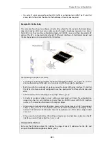
This example shows how to configure a
Radius Relay
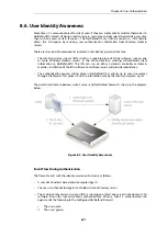
object for the scenario illustrated below.
Here, client devices (UE) must access data services through a backbone network via an Access
Point (AP). First, they must be authenticated against a RADIUS server and then allocated an IP
address. The AP is connected to the physical
If1
Ethernet interface of a NetDefend Firewall and
the backbone network is connected to the
If2
interface.
The following assumptions are made:
•
Two VLANs are already configured and these NetDefendOS objects are called
vlan_auth
for
client authentication traffic and
vlan_data
for data traffic flowing to the backbone.
•
Both these VLANs are already set up to run over the physical Ethernet interface
If1
and that
the AP has also been correctly configured to use the appropriate VLAN for authentication and
data.
•
Authenticated users must belong to the group called
ue_group
.
•
A
Radius Relay
object called
r_relay1
will be created which will listen for authentication
requests on the
vlan_auth
interface and relay them to a RADIUS server with the IPv4 address
radius_ip
. The scenario is illustrated in the diagram below.
•
After successful authentication, IP address leases will be handed out by a DHCP server object
called
rr_dhcp_server
. It is assumed the UEs will be allocated addresses belonging to the
network
192.168.10.10-192.168.10.255
that will be defined in an IPv4 address object called
client_net
.
•
After successful authentication, UEs will be granted access to a backbone network on the
If2
interface using an IP rule called
client_access_rule
.
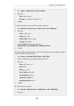
Command-Line Interface
A. Create the
IP4Address
object that defines the range of client IP addresses for the UEs and
assign it the authentication group called
ue_group
:
Chapter 8: User Authentication
655
Summary of Contents for NetDefendOS
Page 30: ...Figure 1 3 Packet Flow Schematic Part III Chapter 1 NetDefendOS Overview 30 ...
Page 32: ...Chapter 1 NetDefendOS Overview 32 ...
Page 144: ...Chapter 2 Management and Maintenance 144 ...
Page 284: ...Chapter 3 Fundamentals 284 ...
Page 392: ...Chapter 4 Routing 392 ...
Page 419: ... Host 2001 DB8 1 MAC 00 90 12 13 14 15 5 Click OK Chapter 5 DHCP Services 419 ...
Page 420: ...Chapter 5 DHCP Services 420 ...
Page 573: ...Chapter 6 Security Mechanisms 573 ...
Page 607: ...Chapter 7 Address Translation 607 ...
Page 666: ...Chapter 8 User Authentication 666 ...
Page 775: ...Chapter 9 VPN 775 ...
Page 819: ...Chapter 10 Traffic Management 819 ...
Page 842: ...Chapter 11 High Availability 842 ...
Page 866: ...Default Enabled Chapter 13 Advanced Settings 866 ...
Page 879: ...Chapter 13 Advanced Settings 879 ...

