


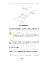

This example illustrates a multiple ISP scenario which is a common use of policy-based routing.
The following is assumed:
•
Each ISP will provide an IPv4 network from its network range. A 2 ISP scenario is assumed in
this case, with the network
10.10.10.0/24
belonging to ISP A and
20.20.20.0/24
belonging to
ISP B. The ISP provided gateways are
10.10.10.1
and
20.20.20.1
respectively.
•
All addresses in this scenario are public addresses for the sake of simplicity.
•
This is a "drop-in" design, where there are no explicit routing subnets between the ISP
gateways and the NetDefend Firewall.
In a provider-independent network, clients will likely have a single IP address, belonging to one
of the ISPs. In a single-organization scenario, publicly accessible servers will be configured with
two separate IP addresses: one from each ISP. However, this difference does not matter for the
policy routing setup itself.
Note that, for a single organization, Internet connectivity through multiple ISPs is normally best
done with the BGP protocol, which means not worrying about different IP spans or about policy
routing. Unfortunately, this is not always possible, and this is where
Policy Based Routing
becomes a necessity.
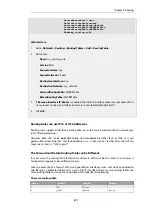
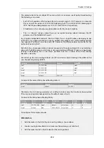
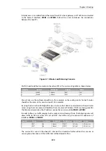
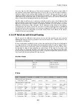
We will set up the main routing table to use ISP A and add a named routing table called
r2
that
uses the default gateway of ISP B.
Interface
Network
Gateway
ProxyARP
lan1
10.10.10.0/24
wan1
lan1
20.20.20.0/24
wan2
wan1
10.10.10.1/32
lan1
wan2
20.20.20.1/32
lan1
wan1
all-nets
10.10.10.1
Contents of the named Policy-based Routing table
r2
:
Interface
Network
Gateway
wan2
all-nets
20.20.20.1
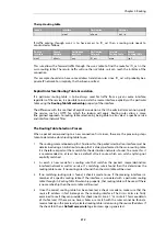
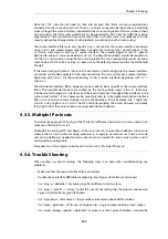
The table
r2
has its
Ordering
parameter set to
Default
, which means that it will only be consulted
if the main routing table lookup matches the default route (
all-nets
).
Contents of the Policy-based Routing Policy:
Source
Interface
Source
Range
Destination
Interface
Destination
Range
Selected/
Service
Forward
VR table
Return
VR table
lan1
10.10.10.0/24
wan1
all-nets
all_services
r2
r2
wan2
all-nets
lan1
20.20.20.0/24
all_services
r2
r2
To configure this example scenario:
Web Interface
1.
Add the routes in the list to the main routing table, as shown above.
2.
Create a routing table called
r2
and make sure the ordering is set to
Default
.
3.
Add the routes found in the list above for the routing table
r2
.
Chapter 4: Routing
314
Summary of Contents for NetDefendOS
Page 30: ...Figure 1 3 Packet Flow Schematic Part III Chapter 1 NetDefendOS Overview 30 ...
Page 32: ...Chapter 1 NetDefendOS Overview 32 ...
Page 144: ...Chapter 2 Management and Maintenance 144 ...
Page 284: ...Chapter 3 Fundamentals 284 ...
Page 392: ...Chapter 4 Routing 392 ...
Page 419: ... Host 2001 DB8 1 MAC 00 90 12 13 14 15 5 Click OK Chapter 5 DHCP Services 419 ...
Page 420: ...Chapter 5 DHCP Services 420 ...
Page 573: ...Chapter 6 Security Mechanisms 573 ...
Page 607: ...Chapter 7 Address Translation 607 ...
Page 666: ...Chapter 8 User Authentication 666 ...
Page 775: ...Chapter 9 VPN 775 ...
Page 819: ...Chapter 10 Traffic Management 819 ...
Page 842: ...Chapter 11 High Availability 842 ...
Page 866: ...Default Enabled Chapter 13 Advanced Settings 866 ...
Page 879: ...Chapter 13 Advanced Settings 879 ...