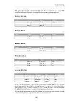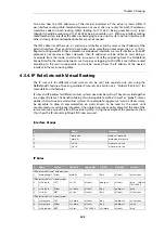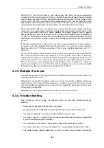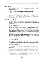
impossible to have an area physically connected to the backbone, a
Virtual Link
is used. Virtual
links can provide an area with a logical path to the backbone area.
This virtual link is established between two
Area Border Routers
(ABRs) that are on one common
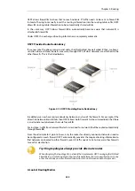
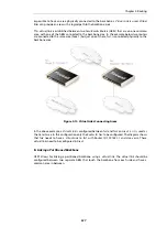
area, with one of the ABRs connected to the backbone area. In the example below two routers
are connected to the same area (Area 1) but just one of them,
fw1
, is connected physically to the
backbone area.
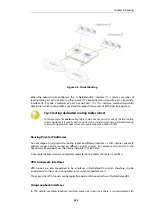
Figure 4.13. Virtual Links Connecting Areas
In the above example, a
Virtual Link
is configured between
fw1
and
fw2
on
Area 1
as it is used as
the transit area. In this configuration only the
Router ID
has to be configured. The diagram shows
that
fw2
needs to have a
Virtual Link
to
fw1
with Router ID
192.168.1.1
and vice versa. These
virtual links need to be configured in
Area 1
.
B. Linking a Partitioned Backbone
OSPF allows for linking a partitioned backbone using a virtual link. The virtual link should be
configured between two separate ABRs that touch the backbone from each side and have a
common area in between.
Chapter 4: Routing
337
Summary of Contents for NetDefendOS
Page 30: ...Figure 1 3 Packet Flow Schematic Part III Chapter 1 NetDefendOS Overview 30 ...
Page 32: ...Chapter 1 NetDefendOS Overview 32 ...
Page 144: ...Chapter 2 Management and Maintenance 144 ...
Page 284: ...Chapter 3 Fundamentals 284 ...
Page 392: ...Chapter 4 Routing 392 ...
Page 419: ... Host 2001 DB8 1 MAC 00 90 12 13 14 15 5 Click OK Chapter 5 DHCP Services 419 ...
Page 420: ...Chapter 5 DHCP Services 420 ...
Page 573: ...Chapter 6 Security Mechanisms 573 ...
Page 607: ...Chapter 7 Address Translation 607 ...
Page 666: ...Chapter 8 User Authentication 666 ...
Page 775: ...Chapter 9 VPN 775 ...
Page 819: ...Chapter 10 Traffic Management 819 ...
Page 842: ...Chapter 11 High Availability 842 ...
Page 866: ...Default Enabled Chapter 13 Advanced Settings 866 ...
Page 879: ...Chapter 13 Advanced Settings 879 ...

