


1-54
SRW-5000/5500
1-25-8. CP-382 Board
After repairing this board
(except for NV-RAM replacement)
1.
Check that the lower control panel functions normally.
2.
Check that the video output signal is correctly dis-
played on the color display (LCD) of the lower control
panel, using the following procedure:
(1) Play back a video tape.
(2) Press the DISPLAY key on the lower control
panel to check that the images being played back
are displayed on the color display.
(3) If necessary, adjust the RGB gain of the color
display. (Refer to Section 3-3-9.)
After replacing the NV-RAM
1.
Turn on the power of the unit while pressing the
[0]
,
[SET]
, and
[CLR]
keys simultaneously.
n
Keep pressing the keys until the confirmation sound is
beeped. This operation initializes the NV-RAM
without a system error caused by its data loss. (The
setting is reset to the value fixed in the ROM).
2.
Adjust the RGB gain of the color display.
(Refer to Section 3-3-9.)
3.
Set the POWER ON BANK RECALL setting data
again. (Refer to the operation manual.)
Board Replacement
Before replacing this board, perform the following.
1.
If possible, take notes of the following setting data:
.
POWER ON BANK RECALL setting data
2.
Confirm that each DIP switch on the new board is the
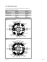
factory setting. (Refer to Section 1-14.)
5.
Remove the backup battery from IC226 on the new
board, and install it again after a while.
(Refer to Section 1-17.)
After the board replacement, perform the procedure of
“After replacing the NV-RAM” above.
1-25-9. CUE-13 Board
After replacing and repairing this board, adjust the CUE
playback system (Section 8-5-4).
1-25-7. CP-378 Board
After replacing and repairing this board, perform the
following checks.
Tools
.
Audio analyzer:
Audio Precision System One or System Two or equiva-
lent
Checks
1.
In the AUDIO menu, perform the following to set all
the audio inputs to AES/EBU. (Refer to the Operation
Manual.)
AUDIO
→
[F1]
(AUDIO IN)
→
[F7]
(AUDIO IN
ALL): AES/EBU
m
.
Confirm that the input displays on the top of the
audio meter are turned into A/E.
.
Before this menu operation, write down the custom-
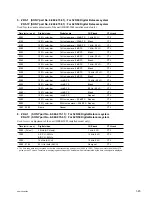
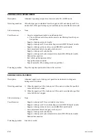
er settings to the following table:
Channel
Customer
Channel
Customer
Setting
Setting
CH1
[||]
SDI
[||]
AES/EBU
CH7
[||]
SDI
[||]
AES/EBU
CH2
[||]
SDI
[||]
AES/EBU
CH8
[||]
SDI
[||]
AES/EBU
CH3
[||]
SDI
[||]
AES/EBU
CH9
[||]
SDI
[||]
AES/EBU
CH4
[||]
SDI
[||]
AES/EBU
CH10
[||]
SDI
[||]
AES/EBU
CH5
[||]
SDI
[||]
AES/EBU
CH11
[||]
SDI
[||]
AES/EBU
CH6
[||]
SDI
[||]
AES/EBU
CH12
[||]
SDI
[||]
AES/EBU
2.
Connect the DIGITAL I/O (AES/EBU) INPUT CH1/2
connector with the AES/EBU output connector of the
audio analyzer.
Also, connect the DIGITAL I/O (AES/EBU) OUT-
PUT CH1/2 connector with the ABS/EBU input
connector of the audio analyzer.
3.
Input the
_
20 dBFs/1 kHz signal from the audio
analyzer, and check that the audio level meters for
CH1 and CH2 indicate
_
20 dB on the color display
(LCD).
4.
Confirm that the level of the AES/EBU input connec-
tor of the audio analyzer is
_
20 dBFs for both the CH1
and CH2.
5.
Perform the same checks for the DIGITAL I/O (AES/
EBU) INPUT/OUTPUT CH3/4 to CH11/12 connec-
tors.
6.
Return the settings of the AUDIO menu, which were
changed for the checks, to the customer settings.
Содержание SRW-5000
Страница 4: ......
Страница 12: ......
Страница 16: ......
Страница 58: ...1 42 SRW 5000 5500 d l l S G L 6 6 d d 4 8 3 7 2 6 0 1 5 9 ...
Страница 78: ......
Страница 194: ......
Страница 376: ......
Страница 398: ......
Страница 438: ...Printed in Japan Sony Corporation 2005 2 08 B P Company 2004 SRW 5000 SY SRW 5500 SY E 9 968 022 03 ...