


8-3
SRW-5000/5500
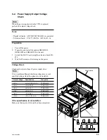
8-2. Power Supply Output Voltage
Check
n
When the power supply unit in the VTR is replaced,
perform the output voltage check.
Tools
.
Digital voltmeter: ADVANTEST R6441B or equivalent
.
Extension board: EX-873 (Part No. A-8346-141-A)
Preparation
1.
Turn off the power.
2.
If possible, and install the options HKSR-5001,
HKSR-5002 and HKSR-5003 to the unit.
3.
Extend the SS-95 board using the extension board EX-
873.
4.
Wait for 10 minutes after turning on the power.
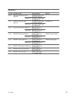
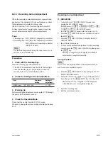
Voltage Check
Check each output voltage of power supply lines.
n
It is no problem although checking voltage may exceed
specified voltage when the options are not installed.
Output voltage
Specification
Test point
+
2.5 V
+
2.5
+
0.22/
_
0.15 V
TP1/EX-873
+
3.4 V
+
3.4
±
0.25 V
TP2/EX-873
+
6.2 V
+
6.2
±
0.3 V
TP3/EX-873
+
15V
+
15
±
1.2 V
TP4/EX-873
_
6.2 V
_
6.2
±
0.6 V
TP5/EX-873
_
15 V
_
15
+
1.8/
_
1.4 V
TP6/EX-873
If the specification is not satisfied
Make sure that repair of this unit had been completed.
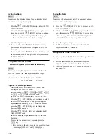
2
E1
TP5
TP6
TP4
TP2
TP3
TP1
TP
_
6.2V TP
+
6.2V
TP
_
15V TP
+
15V TP
+
3.4V
TP
+
2.5V
EX-873
SS-95 board
Содержание SRW-5000
Страница 4: ......
Страница 12: ......
Страница 16: ......
Страница 58: ...1 42 SRW 5000 5500 d l l S G L 6 6 d d 4 8 3 7 2 6 0 1 5 9 ...
Страница 78: ......
Страница 194: ......
Страница 376: ......
Страница 398: ......
Страница 438: ...Printed in Japan Sony Corporation 2005 2 08 B P Company 2004 SRW 5000 SY SRW 5500 SY E 9 968 022 03 ...