


5-30
SRW-5000/5500
CL guide rail
Portion A
Positioning pin
Positioning
hole
Positioning
hole
B3
x
12
B3
x
12
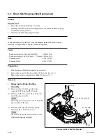
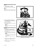
4. Reattaching the CL Guide Rail
(1) Check if the deck is in the unthreading end
state.
(2) Insert the portion A of the CL guide rail to
the bottom of the drum.
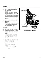
(3) Match and attach the positioning pin of the
CL guide rail to the positioning hole of the
MD base assembly.
(4) Tighten the two screws.
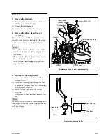
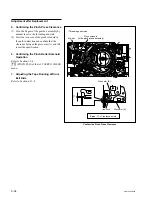
5. Cleaning
Clean the AT head surfaces with a cleaning cloth
moistened with cleaning fluid.
n
After cleaning, wipe with a dry cleaning cloth.
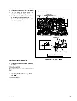
Adjustment after Replacement
6. Adjusting the Tape Running
Refer to Sections 6-2 to 6-11.
7. Electrical Adjustment after Replacing
the AT Head
Refer to Section 7-3.
Reattach the CL Guide Rail
Содержание SRW-5000
Страница 4: ......
Страница 12: ......
Страница 16: ......
Страница 58: ...1 42 SRW 5000 5500 d l l S G L 6 6 d d 4 8 3 7 2 6 0 1 5 9 ...
Страница 78: ......
Страница 194: ......
Страница 376: ......
Страница 398: ......
Страница 438: ...Printed in Japan Sony Corporation 2005 2 08 B P Company 2004 SRW 5000 SY SRW 5500 SY E 9 968 022 03 ...