


5-24
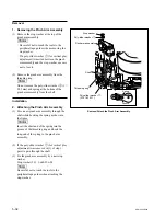
SRW-5000/5500
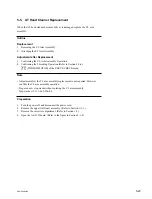
Groove
Spring
The shord-end tip
should be in the
groove.
Hole
CL arm assembly
Threading ring
Spring
M gear
Gear box assembly
DT-47
board
CL arm assembly
Stop washer
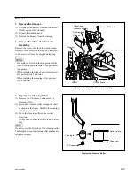
Removal
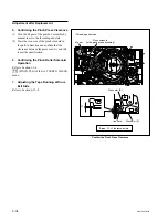
1. Removing the CL Arm Assembly
(1) Turn the M gear of the gear box assembly
manually in the direction of the arrow to
move the CL arm assembly to the position
shown in the figure.
n
Move the CL arm assembly to the front of the
DT-47 board. Otherwise, the CL arm assem-
bly cannot be removed because the stop
washer is hidden by other parts.
(2) Remove the stop washer at the top of the CL
arm assembly.
n
Be careful not to touch the tools to the drum
or peripheral tape guides when removing the
stop washer.
(3) Remove the CL arm assembly from the
threading ring.
n
Do not remove the spring at the bottom of the
CL arm assembly from the shaft.
Installation
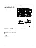
2. Attaching the CL Arm Assembly
(1) Pass a new CL arm assembly through the
shaft while hooking the spring as shown in
the figure.
n
Insert the short-end of spring into the groove
of the threading ring and the long-end of
spring into the hole of the CL arm assembly.
(2) Fix the CL arm assembly by a new stop
washer.
Stop washer (2.3): 3-669-596-00
n
Be careful not to touch the tools to the drum
or peripheral tape guides when attaching the
stop washer.
Remove/Attach the CL Arm Assembly
Содержание SRW-5000
Страница 4: ......
Страница 12: ......
Страница 16: ......
Страница 58: ...1 42 SRW 5000 5500 d l l S G L 6 6 d d 4 8 3 7 2 6 0 1 5 9 ...
Страница 78: ......
Страница 194: ......
Страница 376: ......
Страница 398: ......
Страница 438: ...Printed in Japan Sony Corporation 2005 2 08 B P Company 2004 SRW 5000 SY SRW 5500 SY E 9 968 022 03 ...