


1-39
SRW-5000/5500
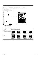
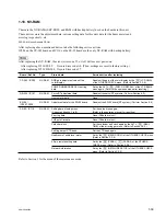
1-18. NV-RAM
There are the NV-RAMs (EEP-ROM, and RAM with backup battery) used on the boards in this unit.
These devices store the adjustment data, various setting data for this unit, data for the hours meters and
error log respectively, etc.
EEP-ROM: Electric Erasable P-ROM
After replacing above-mentioned device, take the following service actions.
IC206 on the CP-382 board and IC116 on the SS-95 board are the only NV-RAM with backup battery.
n
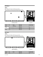
After replacing the NV-RAM, the error (error code 97, or A8) will occur at power-on.
After replacing IC116/SS-95:
Occurs Error code A8. (Then, settings are reset to factory setting.)
After replacing IC101/DR-508: Occurs Error code 97.
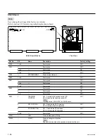
Board / Ref.No.
Type
Stored data
Service action after replacing
CP-382 / IC206
NV-RAM
RGB gain adjustment value of the
Readjust the gain of the color display by the
[F8]
(LCD GAIN)
color display
of the OTHERS CHECK menu. (Refer to Section 3-3-9.)
POWER ON BACK RECALL setting
Set by the ALT
+
[F4]
(POW-ON RECALL) of the VTR BANK
data
menu again. (Refer to the operation manual for resetting.)
DR-508 / IC101
NV-RAM
Servo/DT adjustment data
Readjust the servo/DT systems. (Perform Section 8-3.)
Hours meter data
None
EQ-94 /
NV-RAM
Adjustment data for the EQ-94 board
Readjust the EQ-94 board (RF system). (Perform Section 8-4.)
IC2907, 2908
SS-95 / IC116
NV-RAM
Setting data of setup menu
Set the setup menu again.
(Current and banks 1 to 8)
(Refer to the operation manual for resetting.)
Error log data
None (All data are lost.)
CUE point list data
None (All data are lost.)
Calendar/clock
Set the calendar and clock again by the ALT
+
[F9]
(REAL
TIME) of the error logger menu. (Refer to Section 3-2-3.)
Settting data of VTR bank
Set the VTR bank again.
Headroom of audio level meter
Set by the
[F4]
(HEAD ROOM) of the OTHERS CHECK menu.
(Refer to Section 3-3-9.)
50-pin remote setting data
Set by the
[F6]
(PARA-I),
[F7]
(PARA-0) of the OTHERS
CHECK menu. (Refer to Section 3-3-9.)
Network information
Set by the
[F3]
(NETWORK SETUP) of the OTHERS CHECK
menu. (Refer to Section 3-3-9.)
Refer to Section 3 for the menu of the maintenance mode.
Содержание SRW-5000
Страница 4: ......
Страница 12: ......
Страница 16: ......
Страница 58: ...1 42 SRW 5000 5500 d l l S G L 6 6 d d 4 8 3 7 2 6 0 1 5 9 ...
Страница 78: ......
Страница 194: ......
Страница 376: ......
Страница 398: ......
Страница 438: ...Printed in Japan Sony Corporation 2005 2 08 B P Company 2004 SRW 5000 SY SRW 5500 SY E 9 968 022 03 ...