


6-37
SRW-5000/5500
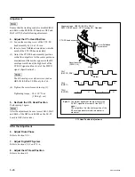
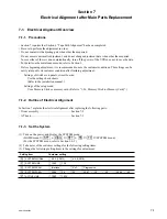
AT head
Securing screw
(PSW3
x
8)
Notch
Securing screw
(PSW3
x
8)
.
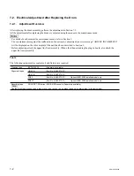
Alignment tape : HR2-1B (00:00 to 20:00)
CTL PULSE
TC PB
A
65
35
50
50
65
35
Spec. : A = 0.15
±
0.40 ms
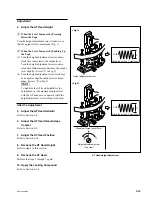
5. Adjust the AT Head Position
(1) Loosen the two securing screws of the AT
head assembly by 1/4 to 1/2 turn.
(2) Turn on the power, then play back the HR2-
1B (00:00 to 20:00) in the PLAY mode.
(3) Insert a 3 mm flatbladed screwdriver into the
notch of the AT head assembly.
(4) Adjust the AT head assembly position so that
the specification is satisfied.
m
.
The specifications in AT head position
check and position adjustment differ. When
adjusting, apply the specification in AT
head position adjustment.
.
The TC signal is in 0.15 ms advance of the
CTL signal.
(5) Tighten the two screws loosened in step (1).
Tightening torque: 98
x
10
_
2
N
.
m
{10.0 kgf
.
cm}
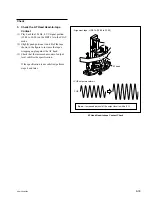
6. Recheck the AT Head Position
Perform previous step 3 in this section again.
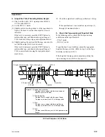
7. Attach the CL Guide Rail
(1) Turn off the power, then remove the align-
ment tape.
(2) Attach the CL guide rail with two screws.
After the Adjustment
8. Check the AT Head Height
Refer to Section 6-7.
9. Check the AT Head Azimuth
Refer to Section 6-8.
10. Check the AT Head Head-to-tape
Contact
Refer to Section 6-9.
11. Check the AT Head Position
Refer to step 3 in this section.
12. Apply the Locking Compound
Refer to Section 6-1-9.
AT Head Position Adjustment
Содержание SRW-5000
Страница 4: ......
Страница 12: ......
Страница 16: ......
Страница 58: ...1 42 SRW 5000 5500 d l l S G L 6 6 d d 4 8 3 7 2 6 0 1 5 9 ...
Страница 78: ......
Страница 194: ......
Страница 376: ......
Страница 398: ......
Страница 438: ...Printed in Japan Sony Corporation 2005 2 08 B P Company 2004 SRW 5000 SY SRW 5500 SY E 9 968 022 03 ...