


5-1
SRW-5000/5500
1
@-
2
6
@=
0
![
!=
!;
!\
!]
!-
!/
@=
!'
!.
5
7
4
8
!,
9
3
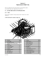
Section 5
Replacement of Main Parts
This section explains the replacement procedures of periodic replacement parts,
main mechanical parts, power supply unit, and circuit boards.
5-1. General Information for Parts Replacement
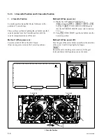
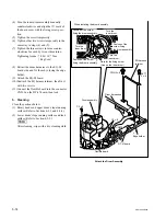
5-1-1. Index
The parts that are explained each replacement procedure in Section 5 are as shown
in the below.
(1) Mechanical parts and power supply unit
No.
Part name
Section
1
Drum Assembly
5-2
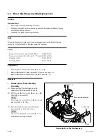
2
Brush Slip Ring Assembly
5-3
3
Cleaning Roller and Video Head Cleaner
5-4
Assembly
4
AT Head Cleaner
5-5
5
CTL/FE Head Assembly
5-6
6
AT Head Assembly
5-7
7
Pinch Roller
5-8
8
Pinch Press Assembly
5-9
9
Capstan Motor
5-10
!/
Reel Table Assembly
5-11
!-
Brake Assembly (S)
5-12
No.
Part name
Section
!=
Brake Assembly (T)
5-12
![
Reel Motor Assembly (S)
5-13
!]
Reel Motor Assembly (T)
5-13
!\
Motor Holder Assembly
5-14
!;
Worm Assembly
5-15
_
Tape Guide
5-16
!'
S Plate Assembly
5-16-1
!,
Gear Box Assembly/Threading Motor
5-17
!.
Threading Ring Assembly
5-18
@/
S Tension Regulator Assembly
5-19
@-
T Tension Regulator Assembly
5-20
@=
T Drawer Assembly
5-21
Содержание SRW-5000
Страница 4: ......
Страница 12: ......
Страница 16: ......
Страница 58: ...1 42 SRW 5000 5500 d l l S G L 6 6 d d 4 8 3 7 2 6 0 1 5 9 ...
Страница 78: ......
Страница 194: ......
Страница 376: ......
Страница 398: ......
Страница 438: ...Printed in Japan Sony Corporation 2005 2 08 B P Company 2004 SRW 5000 SY SRW 5500 SY E 9 968 022 03 ...