


6-14
SRW-5000/5500
.
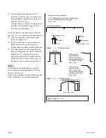
Alignment tape : HR2-1B (00:00 to 20:00)
S802-1/SS-95 board : ON (Tracking VR : Enabled)
<SS-95 board, side A>
TG-0
TG-1
<Fig.2> CH-1 : TP52/EQ-94 board
<Fig.3> CH-1 : TP52/EQ-94 board
A
B
RF max
A = RF max
x
0.8
(B is 80 to 90 % of A)
<Fig.1>
No contact
Tape
Upper flange of TG-2
Marker
Marker
A
B
C
D
E
F
G
H
J
K
L
M
N
S802
RV1001 (Tracking VR)
P
1
2
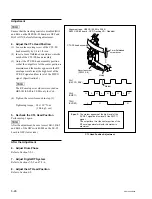
RF max
If the pressure against the
tape at TG-1 is too much,
the waveform becomes as
shown in the upper figure.
(NG)
If the pressure against the
tape at TG-2 is too much,
the waveform becomes as
shown in the upper figure.
(NG)
TG-2
height adjustment nut
TG-1
height adjustment nut
The RF envelope waveform is flat.
Spec.9 :
A
B
C
D
E
F
G
H
J
K
L
M
N
P
1
2
TP52
TP5
<EQ-94 board, side A>
CH-1 : TP52/EQ-94 board (CNF CG ENV signal)
CH-2 : TP5/EQ-94 board (SWP5 signal)
TRIG : CH-2
.
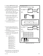
Connection of the oscilloscope
1. Adjust the Tracking at the Tape
Entrance Side
(1) Set Bit-1 of the DIP switch S802 on the SS-
95 board to ON (upper side) to enable the
tracking control.
(2) Play back the alignment tape HR2-1B (00:00
to 20:00) in the PLAY mode.
(3) Rotate the tracking VR (RV1001/SS-95
board) clockwise to set the center of the RF
envelope waveform to 80 % of the maximum
output level.
(4) Loosen the height adjustment nut of TG-2
(rotate it counterclockwise) so that the tape
does not in contact the upper flange. (Fig. 1)
(5) Rotate the height adjustment nut of TG-1 to
make the RF envelope waveform as shown in
Fig. 2.
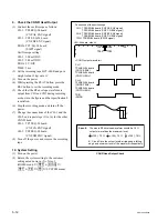
n
If this adjustment is performed again because
the specification 10 described after was not
satisfied, rotate the height adjustment nut of
TG-1 a little with the RF envelope waveform
appearing as in Fig. 2, to make the level B of
the entrance side higher than before.
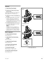
(6) Rotate the height adjustment nut of TG-2
clockwise to adjust the height of TG-2 until
the waveform satisfies the specification 9.
(Fig. 3)
If the waveform does not satisfy the specifi-
cation (does not become flat), perform the
following adjustment (
1
and
2
), and return
to step (4).
1
Clean the lower drum lead with a wooden
stick. (Refer to Section 4-2-5.)
2
While running the tape, press the tape lightly
with the wooden stick and check that the tape
does not float from the lead.
Tracking Adjustment at Tape Entrance Side (PLAY)
Содержание SRW-5000
Страница 4: ......
Страница 12: ......
Страница 16: ......
Страница 58: ...1 42 SRW 5000 5500 d l l S G L 6 6 d d 4 8 3 7 2 6 0 1 5 9 ...
Страница 78: ......
Страница 194: ......
Страница 376: ......
Страница 398: ......
Страница 438: ...Printed in Japan Sony Corporation 2005 2 08 B P Company 2004 SRW 5000 SY SRW 5500 SY E 9 968 022 03 ...