


5-3
SRW-5000/5500
Board name Procedure
Steps after
replacement
PTC-99
Refer to the exploded views
Section 1-25-28
(Replace by the MC sensor
Assembly.)
RX-80
Refer to Section 1-12 and the
Section 1-25-29
exploded views
SE-606A
Section 5-13
Section 1-25-30
SS-95
Section 1-12 (Plug-in board)
Section 1-25-31
SWC-43
Section 5-30-16
Section 1-25-32
TC-104
Section 5-30-18
Section 1-25-33
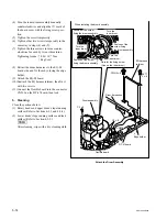
TR-119
Section 5-19 (Replace by the S
Section 1-25-34
tension regulator.)
TR-120
Section 5-20 (Replace by the T
Section 1-25-35
tension regulator.)
TX-96
Refer to Section 1-12 and the
Section 1-25-36
exploded views
VPR-79
Section 1-12 (Plug-in board)
Section 1-25-37
For the exploded views, refer to the maintenance manual volume 2.
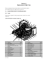
(2) Mounted Circuit Boards
n
After replacing the mounted circuit boards (or the assem-
bling parts including them), perform the steps after re-
placement. (Refer to Section 1-25.)
Board name Procedure
Steps after
replacement
AE-31H
Section 5-30-1
Section 1-25-1
APR-62
Section 1-12 (Plug-in board)
Section 1-25-2
CCM-15
Section 5-17
Section 1-25-3
(Replace by the Gear Box
Assembly.)
CL-29
Section 5-30-2
Section 1-25-4
CP-376/
Section 5-30-3
Section 1-25-5
CP-376A
CP-377
Section 5-30-4
Section 1-25-6
CP-378
Section 5-30-5
Section 1-25-7
CP-382
Section 5-30-6
Section 1-25-8
CUE-13
Section 5-30-7
Section 1-25-9
DIO-69
Section 5-30-8
Section 1-25-10
DR-508
Section 5-30-9
Section 1-25-11
DT-47
Section 5-30-10
Section 1-25-12
EQ-94
Section 1-12 (Plug-in board)
Section 1-25-13
FP-131
Section 5-30-11
Section 1-25-14
FP-132
Section 5-30-11
Section 1-25-15
HIF-8
Section 1-12 (Plug-in board)
Section 1-25-16
HN-268
Refer to the exploded views
Section 1-25-17
HP-110
Section 5-30-12
Section 1-25-18
HPR-8/
Section 1-12 (Plug-in board)
Section 1-25-19
HPR-8A
IRC-5/
Section 1-12 (Plug-in board)
Section 1-25-20
IRC-5A
KY-526
Refer to Section 5-30-13
Section 1-25-21
KY-527
Refer to Section 5-30-14
Section 1-25-21
LED-386
Section 5-30-15
Section 1-25-22
LP-81
Refer to Section 1-5 (Removing/
Section 1-25-23
Installing the cassette
compartment) and the exploded
views
MB-964
Section 5-30-17
Section 1-25-24
PC-70
Section 1-5 (Replace by the
Section 1-25-25
Cassette Compartment Assembly.)
PTC-101
Refer to Section 5-25
Section 1-25-26
(Replace by the Search Dial
Assembly.)
PTC-102
Section 5-17 (Replace by the
Section 1-25-27
Gear Box Assembly.)
Содержание SRW-5000
Страница 4: ......
Страница 12: ......
Страница 16: ......
Страница 58: ...1 42 SRW 5000 5500 d l l S G L 6 6 d d 4 8 3 7 2 6 0 1 5 9 ...
Страница 78: ......
Страница 194: ......
Страница 376: ......
Страница 398: ......
Страница 438: ...Printed in Japan Sony Corporation 2005 2 08 B P Company 2004 SRW 5000 SY SRW 5500 SY E 9 968 022 03 ...