


5-59
SRW-5000/5500
TG-9
M gear
Gear box assembly
5-17. Gear Box Assembly Replacement
Outline
Replacement
1.
Removing the Video Head Cleaner Assembly
(Refer to steps 1 and 2 in Section 5-4.)
2.
Shifting the TG-9
3.
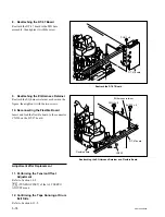
Disconnecting the Harness (CN233/HN-268 Board)
4.
Removing the Gear Box Assembly
5.
Attaching the Gear Box Assembly
6.
Reconnecting the Harness (CN233/HN-268 Board)
7.
Reattaching the Video Head Cleaner Assembly
(Refer to steps 4 to 6 in Section 5-4.)
Adjustment after Replacement
8.
Confirming the Threading Motor Operation (Refer to Section 3-3-4.)
[F7]
(THREAD MOTOR) of the SERVO CHECK menu
Preparation
1.
Turn the power off and disconnect the power cord.
2.
Remove the upper lid (front) assembly. (Refer to Section 1-3-1.)
3.
Remove the cassette compartment. (Refer to Section 1-5.)
4.
Open the AE-31H board. (Refer to the figure in Section 5-1-2.)
Removal
1. Removing the Video Head Cleaner
Assembly
(Refer to steps 1 and 2 in Section 5-4.)
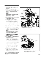
2. Shifting the TG-9
Turn the M gear of the gear box assembly in the
arrow direction to shift the TG-9 to the position
as shown in the figure.
n
Move the TG-9 so that enough space to remove
the gear box assembly is made.
Shift the TG-9
Содержание SRW-5000
Страница 4: ......
Страница 12: ......
Страница 16: ......
Страница 58: ...1 42 SRW 5000 5500 d l l S G L 6 6 d d 4 8 3 7 2 6 0 1 5 9 ...
Страница 78: ......
Страница 194: ......
Страница 376: ......
Страница 398: ......
Страница 438: ...Printed in Japan Sony Corporation 2005 2 08 B P Company 2004 SRW 5000 SY SRW 5500 SY E 9 968 022 03 ...