


6-11
SRW-5000/5500
A1
Maximize
Maximize
A1
E1
E1
L
H
L
H
A
B
C
D
E
F
G
H
J
K
L
M
N
P
1
2
3
TP88
TP84
TP96
TP92
TP74
TP62
TP66
TP70
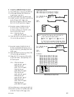
<EQ-94 board, A side>
.
Alignmant tape : HR5-1B
S802-1/SS-95 board : ON (Tracking VR : Enabled)
S802-3/SS-95 board : ON (DT operation : Stopped)
CH-1 : TP66/EQ-94 board
(ADV AE1 ENV)
CH-1 : TP66/EQ-94 board
(ADV AE1 ENV)
TRIG
(SWP1)
TRIG
(SWP1)
A
B
C
D
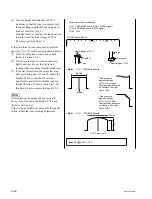
CH-1: TP66/EQ-94 board (ADV AE1 ENV signal)
TP74/EQ-94 board (ADV BF1 ENV signal)
TP88/EQ-94 board (ADV CG1 ENV signal)
TP96/EQ-94 board (ADV DH1 ENV signal)
TP62/EQ-94 board (ADV AE2 ENV signal)
TP70/EQ-94 board (ADV BF2 ENV signal)
TP84/EQ-94 board (ADV CG2 ENV signal)
TP92/EQ-94 board (ADV DH2 ENV signal)
.
Oscilloscope
B
A
Spec.7 :
x
100
>
70 %
C
A
x
100
>
70 %
D
A
x
100
>
70 %
B, C, and D are the output levels at rising edge, falling
edge, and minimum level of the waveform, respectively.
The whole RF envelope waveform should be 70 %
output or more than the maximum level.
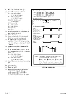
ADVANCE Head Contact Check
8. Check the ADVANCE Head Contact
(1) Turn off the power, and remove the HR2-1B.
(2) Set the alignment tape HR5-1B and put a
weight (about 1 kg) onto it.
(3) Play back the HR5-1B in the PLAY mode.
(4) Set Bit-1 and Bit-3 of the DIP switch S802 on
the SS-95 board to ON (upper side).
Bit-1 ON: The tracking control is enabled.
Bit-3 ON: The DT operation is stopped.
(5) Rotate the tracking VR (RV1001/SS-95
board) clockwise to maximize the RF
envelope waveform A1 of the CH-1 at the
low level of the SWP1 signal.
CH-1: TP66/EQ-94 board
(ADV AE1 ENV signal)
(6) Check that the RF envelope waveform of the
CH-1 satisfy the specification 7.
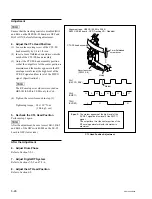
(7) Rotate the tracking VR (RV1001/SS-95
board) to maximize the RF envelope wave-
form E1 of the CH-1 at the high level of the
SWP1 signal.
(8) Check that the RF envelope waveform of the
CH-1 satisfy the specification 7.
(9) Change the CH-1 connection of the oscillo-
scope to the follows, and repeat steps (5) to
(8) for all signals.
CH-1: TP74/EQ-94 board
(ADV BF1 ENV signal)
TP88/EQ-94 board
(ADV CG1 ENV signal)
TP96/EQ-94 board
(ADV DH1 ENV signal)
TP62/EQ-94 board
(ADV AE2 ENV signal)
TP70/EQ-94 board
(ADV BF2 ENV signal)
TP84/EQ-94 board
(ADV CG2 ENV signal)
TP92/EQ-94 board
(ADV DH2 ENV signal)
(10)Turn off the power, and remove the HR5-1B.
(11)Reset Bit-1 and Bit-3 of the DIP switch S802
on the SS-95 board to OFF (upper side).
Содержание SRW-5000
Страница 4: ......
Страница 12: ......
Страница 16: ......
Страница 58: ...1 42 SRW 5000 5500 d l l S G L 6 6 d d 4 8 3 7 2 6 0 1 5 9 ...
Страница 78: ......
Страница 194: ......
Страница 376: ......
Страница 398: ......
Страница 438: ...Printed in Japan Sony Corporation 2005 2 08 B P Company 2004 SRW 5000 SY SRW 5500 SY E 9 968 022 03 ...