


6-32
SRW-5000/5500
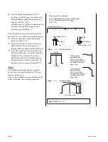
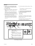
CH-1 : TP300/AE-31H board (CUE signal)
<AE-31H board, side A>
.
Connection of the oscilloscope
TP300
A
B
C
D
E
F
1
2
3
4
5
6
6-9. AT Head Head-to-tape Contact Check and Adjustment
Precaution
The AT head head-to-tape contact adjustment is closely related to the head position
adjustment, head height adjustment, and head azimuth adjustment.
Be sure to adjust (or check) these related portions according to “After the Adjust-
ment” in this section after adjusting the AT head head-to-tape contact.
Tools
.
Alignment tape HR2-1A:
8-960-076-11
.
Oscilloscope (Tektronix TDS3054B or equivalent)
.
Torque screwdriver (6 kgf
.
cm) (JB-5251):
J-6252-510-A
.
Torque screwdriver’s bit (
+
2 mm, l = 75 mm): J-6323-420-A
Preparation
Preparation
1. Set the Alignment Tape
(1) Turn off the power.
(2) Set the HR2-1A, and put a weight (about 1
kg) onto it.
(3) Turn on the power.
2. Connect the Oscilloscope
Connect the oscilloscope as follows:
CH-1:
TP300/AE-31H board (CUE signal)
Oscilloscope setting:
CH-1:
200 mV/DIV
TIME: 5 ms/DIV
Содержание SRW-5000
Страница 4: ......
Страница 12: ......
Страница 16: ......
Страница 58: ...1 42 SRW 5000 5500 d l l S G L 6 6 d d 4 8 3 7 2 6 0 1 5 9 ...
Страница 78: ......
Страница 194: ......
Страница 376: ......
Страница 398: ......
Страница 438: ...Printed in Japan Sony Corporation 2005 2 08 B P Company 2004 SRW 5000 SY SRW 5500 SY E 9 968 022 03 ...