


7-1
SRW-5000/5500
Section 7
Electrical Alignment after Main Parts Replacement
7-1. Electrical Alignment Overview
7-1-1. Precautions
.
Section 7 requires that Section 6 “Tape Path Alignment” has been completed.
.
Be sure to perform the adjustment in order.
.
Do not contact with adjusting part when other than required.
.
Do not execute automatic adjustment, and do not change adjustment data when other than required.
In case either of these is done unintentionally, turn off the power of the VTR so as not to save the data.
.
For details on the maintenance mode, refer to Section 3.
.
Before beginning adjustment, it is recommended to note the customer conditions. The settings can be
easily returned to its customer condition after finishing adjustment.
Settings of switches on panels, circuit boards:
Use the setting check sheets.
(Refer to the installation manual.)
Settings of the setup menu:
Use a Memory Stick or memory card. (Refer to “1-26. Memory Stick (or Memory Card)”.)
7-1-2. Outline of Electrical Alignment
In Section 7 explains the electrical alignment after replacing the following parts:
.
Drum assembly .............................................. Section 7-2
.
AT head .......................................................... Section 7-3
7-1-3. Set the System
(1) Turn on the power, and display the SYSTEM menu.
(HOME menu
→
[SFT]
+
[DIAG]
→
[SFT]
+
[F8]
→
[F9]
→
SYSTEM menu)
(For the SYSTEM menu, refer to Section 3-3-9.)
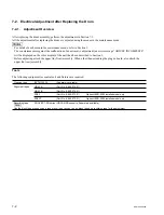
(2) Take notes of the customer settings for the following setting items.
(3) Change the following setting items to the settings for adjustment.
Setting item
Customer setting
[F4]
SYSTEM SIGNAL
[||]
4:2:2 (YPbPr)
[||]
4:4:4 (RGB)
[F1]
SYSTEM LINE
[||]
1080
[||]
720
[F2]
SYSTEM SCAN
[||]
Interlace
[||]
PsF
[||]
Progressive
[F3]
SYSTEM FREQ.
[||]
23.98
[||]
24
[||]
25
[||]
29.97
[||]
30
[||]
50
[||]
59.94
[||]
60
[F7]
ACTIVE LINE
[||]
1080
[||]
1035
Содержание SRW-5000
Страница 4: ......
Страница 12: ......
Страница 16: ......
Страница 58: ...1 42 SRW 5000 5500 d l l S G L 6 6 d d 4 8 3 7 2 6 0 1 5 9 ...
Страница 78: ......
Страница 194: ......
Страница 376: ......
Страница 398: ......
Страница 438: ...Printed in Japan Sony Corporation 2005 2 08 B P Company 2004 SRW 5000 SY SRW 5500 SY E 9 968 022 03 ...