


6-19
SRW-5000/5500
TG-4
AT head
TG-3
AT head
Zenith adjustment screw
B
A
.
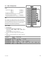
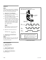
Alignment tape : HR2-1B (00:00 to 20:00)
S802-1/SS-95 board : ON (Tracking VR : Enabled)
<Fig.1> CH-1 : TP52/EQ-94 board
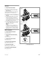
Upper flange of TG-3
Lower flange of TG-4
Lower flange of TG-3
Tape
No contact
No contact
Tape
RF max
A = RF max
x
0.95
Spec.14 : B
x
100 = 50
±
50 %
A
A
B
C
D
E
F
G
H
J
K
L
M
N
S802
RV1001 (Tracking VR)
P
1
2
<SS-95 board, side A>
A
B
C
D
E
F
G
H
J
K
L
M
N
P
1
2
TP52
TP5
<EQ-94 board, side A>
CH-1 : TP52/EQ-94 board (CNF CG ENV signal)
CH-2 : TP5/EQ-94 board (SWP5 signal)
TRIG : CH-2
.
Connection of the oscilloscope
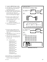
2. Adjust the Tracking at the Tape Exit
Side
(1) Set Bit-1 of the DIP switch S802 on the SS-
95 board to ON (upper side) to enable the
manual tracking control.
(2) Turn on the power, then play back the
alignment tape HR2-1B (00:00 to 20:00) in
the PLAY mode.
(3) Rotate the tracking VR (RV1001/SS-95
board) counterclockwise to set the center of
the RF envelope waveform to 95 % of the
maximum output level.
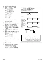
(4) Turn the height adjustment nut of TG-3
counterclockwise by one to two turns so that
the tape does not in contact with the upper
flange of TG-3.
n
Don’t turn excessively the nut, or the tape
bottom edge does in contact with the lower
flange of TG-3.
(5) Turn the height adjustment nut of TG-4
clockwise so that the tape does not in contact
with the lower flange of TG-4.
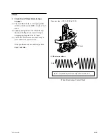
(6) Check that the RF envelope waveform
satisfies the specification 14. (Fig. 1)
If the specification 14 is satisfied, perform
the step (8) and later.
If not, perform the step (7) and later.
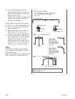
(7) Turn the zenith adjustment screw of the AT
head so that the left portion of the RF enve-
lope waveform becomes 0 to 100 % or less of
the center output level. (specification 14)
At this time, check that the tape does not in
contact with both upper flange of TG-3 and
lower flange of TG-4.
If the tape contacts either flange, repeat step
(4) or (5).
n
If the tape moves upward or downward
following the guide flange movement,
perform the following adjustment.
This trouble cause is uneven tape tension at
upside or downside of the tape caused by AT
head zenith.
.
If the tape moves upward at TG-3:
Turn the zenith adjustment screw
counterclockwise.
.
If the tape moves downward at TG-4:
Turn the zenith adjustment screw clockwise.
Содержание SRW-5000
Страница 4: ......
Страница 12: ......
Страница 16: ......
Страница 58: ...1 42 SRW 5000 5500 d l l S G L 6 6 d d 4 8 3 7 2 6 0 1 5 9 ...
Страница 78: ......
Страница 194: ......
Страница 376: ......
Страница 398: ......
Страница 438: ...Printed in Japan Sony Corporation 2005 2 08 B P Company 2004 SRW 5000 SY SRW 5500 SY E 9 968 022 03 ...