


5-110
SRW-5000/5500
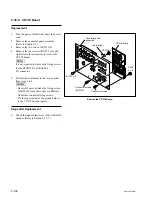
CN301
CN1
CN601
CN503
CN700
CN502
PSW3
x
6
PSW3
x
6
PSW3
x
6
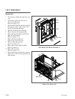
KY-527 board
CP-382 board
Harnesses
CP-382 board
CN-2511 board
CN-2511 board
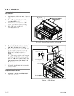
Attach the CP-382 Board
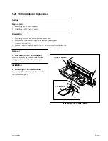
12. Connect the two flexible card wires discon-
nected in step 6.
13. Connect the CN-2511 board to the connector
CN301 on the CP-382 board as shown in the
figure.
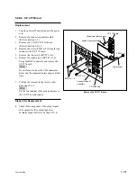
14. Reinstall the CP-382 board to the key panel
frame, then fix it with the five screws.
Tightening torque: 80
x
10
_
2
N
.
m
{8.0 kgf
.
cm}
m
.
Be sure not to be caught the harnesses
shown in the figure between the key panel
frame and CP-382 board.
.
Connect the connector CN503 on the CP-
382 board to the CN1 on the KY-527 board
surely.
15. Connect the harness disconnected in step 4 to
the connector CN601 on the CP-382 board.
16. Reattach the rear cover.
(Refer to step 4 in Secion 5-25.)
17. Reattach thecontrol panel assembly to the
unit. (Refer to Section 1-6.)
Steps after Replacement
18. After replacing the CP-382 board, perform
the “After replacing the NV-RAM” in
Section 1-25-8.
Содержание SRW-5000
Страница 4: ......
Страница 12: ......
Страница 16: ......
Страница 58: ...1 42 SRW 5000 5500 d l l S G L 6 6 d d 4 8 3 7 2 6 0 1 5 9 ...
Страница 78: ......
Страница 194: ......
Страница 376: ......
Страница 398: ......
Страница 438: ...Printed in Japan Sony Corporation 2005 2 08 B P Company 2004 SRW 5000 SY SRW 5500 SY E 9 968 022 03 ...