


6-10
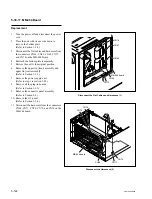
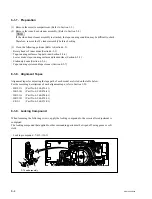
SRW-5000/5500
A
CH-1 : TP52/EQ-94 board
(CNF CG ENV)
B
A
C
.
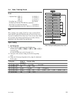
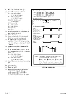
Alignment tape : HR2-1B (00:00 to 20:00)
S802-1/SS-95 board : OFF (Tracking VR : Disabled)
Spec.5 :
x
100
>
70 %
Output levels (B and C) at the tape entrance side and
exit side are more than 70 % of the center level (A).
A
B
x
100
>
70 %
A
C
Video Tracking Check (REV
x
x
x
x
x
10)
6. Check in the REV
x
x
x
x
x
10 Mode
(1) Play back the HR2-1B (00:00 to 20:00).
(2) Set the REV
x
10 mode, and check that the
RF envelope waveform satisfies specification
5.
If specification 5 is not satisfied, perform the
adjustment in the Section 6-3 (Tape Entrance
Side) or Section 6-4 (Tape Exit Side).
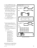
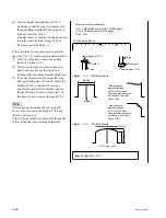
7. Check in the F.FWD and REW Modes
(1) Connect the oscilloscope as follows:
CH-1: TP66/EQ-94 board
(ADV AE1 ENV signal)
CH-2: TP62/ EQ-94 board
(ADV AE2 ENV signal)
TRIG: TP1/ EQ-94 board (SWP1 signal)
Oscilloscope setting
CH-1: 100 to 200 mV/DIV
CH-2: 100 to 200 mV/DIV
TIME: 0.5 to 1 ms/DIV
(2) Play back the HR2-1B (00:00 to 20:00).
(3) Set the F.FWD mode, and check that the RF
envelope waveform of the CH-1 satisfies
specification 6.
(4) Set the REW mode, and check that the RF
envelope waveform of the CH-1 satisfies
specification 6.
(5) Set the F.FWD mode, and check that the RF
envelope waveform of the CH-2 satisfies
specification 6.
(6) Set the REW mode, and check that the RF
envelope waveform of the CH-2 satisfies
specification 6.
If specification 6 is not satisfied, connect the
oscilloscope as follows and perform the
adjustment in the Section 6-3 (Tape Entrance
Side) or Section 6-4 (Tape Exit Side).
CH-1: TP52/EQ-94 board
(CNF CG ENV signal)
CH-2: TP5/ EQ-94 board (SWP5)
TRIG: Set CH-2 as TRIG input.
Oscilloscope setting
CH-1: 100 to 200 mV/DIV
CH-2: 5V/DIV
TIME: 0.5 to 1 ms/DIV
Video Tracking Check (F.FWD, REW)
A
B
A
C
Spec.6 :
x
100
>
70 %
Output levels (B and C) at the tape entrance side and
exit side are more than 70 % of the center level (A).
Check that waveforms appear with no lacking.
A
B
x
100
>
70 %
A
C
A
B
C
D
TP66
TP62
TP52
TP5 TP1
E
F
G
H
J
K
L
M
N
P
1
2
3
.
Alignment tape : HR2-1B (00:00 to 20:00)
S802-1/SS-95 board : OFF (Tracking VR : Disabled)
<EQ-94 board, side A>
CH-1 : TP66/EQ-94 board (ADV AE1 ENV signal)
CH-2 : TP62/EQ-94 board (ADV AE2 ENV signal)
TRIG : TP1/EQ-94 board (SWP1 signal)
.
Connection of the oscilloscope
A
B
C
D
E
F
G
H
J
K
L
M
N
P
1
2
TP52
TP5
<EQ-94 board, side A>
CH-1 : TP52/EQ-94 board (CNF CG ENV signal)
CH-2 : TP5/EQ-94 board (SWP5 signal)
TRIG : CH-2
.
Connection of the oscilloscope
Oscilloscope Connection (Spec.6 is NG)
Содержание SRW-5000
Страница 4: ......
Страница 12: ......
Страница 16: ......
Страница 58: ...1 42 SRW 5000 5500 d l l S G L 6 6 d d 4 8 3 7 2 6 0 1 5 9 ...
Страница 78: ......
Страница 194: ......
Страница 376: ......
Страница 398: ......
Страница 438: ...Printed in Japan Sony Corporation 2005 2 08 B P Company 2004 SRW 5000 SY SRW 5500 SY E 9 968 022 03 ...