


6-29
SRW-5000/5500
Adjustment
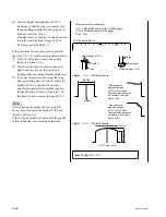
4. Adjust the AT Head Height
A
When the Level Increases by Pressing
Down the Tape
Turn the height adjustment screw clockwise so
that the output level is maximum. (Fig. 1)
B
When the Level Increases by Pushing Up
the Tape
(1) Turn the height adjustment screw counter-
clockwise to maximize the output level.
Turn the height adjustment screw counter-
clockwise furthermore to decrease the output
level slightly. (Arrow
1
in Fig. 2)
(2) Turn the height adjustment screw clockwise
and adjust so that the output level is maxi-
mum. (Arrow
2
in Fig. 2)
n
To stabilize the AT head height after the
adjustment, set the maximum output level
with the AT head moved upward (with the
height adjustment screw turned clockwise).
After the Adjustment
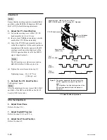
5. Adjust the AT Head Azimuth
Refer to Section 6-8.
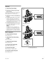
6. Adjust the AT Head Head-to-tape
Contact
Refer to Section 6-9.
7. Adjust the AT Head Position
Refer to Section 6-10.
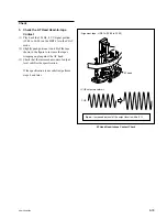
8. Recheck the AT Head Height
Refer to step 3 in this section.
9. Recheck the AT Head
Perform the steps 5 through 7 again.
10. Apply the Locking Compound
Refer to Section 6-1-9.
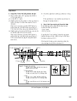
AT Head Height Adjustment
Height adjustment screw
Make the portion C maximize.
CUE
C
<Fig.1>
<Fig.2>
Height adjustment screw
(Top view)
Maximum Output Level Point
1
2
Make the portion C maximize.
CUE
C
Содержание SRW-5000
Страница 4: ......
Страница 12: ......
Страница 16: ......
Страница 58: ...1 42 SRW 5000 5500 d l l S G L 6 6 d d 4 8 3 7 2 6 0 1 5 9 ...
Страница 78: ......
Страница 194: ......
Страница 376: ......
Страница 398: ......
Страница 438: ...Printed in Japan Sony Corporation 2005 2 08 B P Company 2004 SRW 5000 SY SRW 5500 SY E 9 968 022 03 ...