


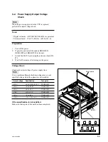


7-11
SRW-5000/5500
7-3. Electrical Adjustment after Replacing the AT Head
7-3-1. Adjustment Overview
Perform this section when the AT head was replaced.
For adjustment items and its order, refer to “Adjustments” as follows.
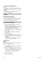
Tools
The following equipment (or equivalent) and fixtures are required:
Audio signal generator
TEKTRONIX SG5010
Audio analyzer
AUDIO PRECISION System One (SYS-22A)
or System Two (SYS-2022A)
n
The audio analyzer should be filtered through 80 kHz LPF throughout adjustment.
Frequency counter
ADVANTEST R5362B
Band-pass filter (1 kHz)
Time code generator
SONY BVG-1600
SONY BVG-1600PS
Time code reader
SONY BVG-1500
SONY BVG-1500PS
Oscilloscope
TEKTRONIX TDS3054B or equivalent
Extension board
EX-949
(Part No. A-8347-714-A)
Alignment tapes
HR5-1A
(Part No. 8-960-076-01)
HR5-1B
(Part No. 8-960-076-31)
Recording tape
Sony BCT-SR series (HDCAM SR cassette: Separately avilable)
n
Use the blank tape erased using a tape eraser in advance or a new blank tape as a recording tape for the adjustment.
Shorting clip
Содержание SRW-5000
Страница 4: ......
Страница 12: ......
Страница 16: ......
Страница 58: ...1 42 SRW 5000 5500 d l l S G L 6 6 d d 4 8 3 7 2 6 0 1 5 9 ...
Страница 78: ......
Страница 194: ......
Страница 376: ......
Страница 398: ......
Страница 438: ...Printed in Japan Sony Corporation 2005 2 08 B P Company 2004 SRW 5000 SY SRW 5500 SY E 9 968 022 03 ...