


1-38
SRW-5000/5500
4.
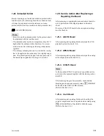
Insert a flat blade driver between the battery and
IC206 to remove the battery.
5.
Install a new battery, ensuring that the marks on the
battery and IC206 are aligned.
6.
Reattach the rear cover to the lower control panel
using the eight screws.
7.
Reattach the lower control panel to the unit.
(Refer to Section 1-6.)
8.
Turn on the power of the unit while pressing the
[0]
,
[SET]
, and
[CLR]
keys simultaneously.
n
Keep pressing the keys until the confirmation sound is
beeped. This operation initializes the NV-RAM
without a system error caused by its data loss. (The
setting is reset to the value fixed in the ROM.)
9.
Perform the following settings again. (Refer to the
“Service action after replacing” in Section 1-18.)
.
RGB gain adjustment value of the color display
.
POWER ON BANK RECALL setting data
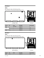
CP-382 board
Mark
Driver
IC206
Mark
Battery
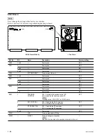
IC116
Mark
Battery
Mark
SS-95 board
Driver
For IC116 on the SS-95 board
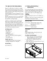
1.
If possible, save the settings of the Setup menu
(current and all banks) into a Memory Stick. (Refer to
Section 1-26.)
2.
If possible, take notes of the following setting data:
.
VTR bank data
.
Headroom of the audio level meter
.
50 pin remote setting data
.
Network information
3.
Remove the SS-95 board. (Refer to Section 1-12.)
4.
Insert a flat blade driver between the battery and
IC116 to remove the battery.
5.
Install a new battery, ensuring that the marks on the
battery and IC116 are aligned.
6.
Reinstall the SS-95 board.
7.
Turn on the power of the unit while pressing the
[0]
,
[SET]
, and
[CLR]
keys simultaneously.
n
Keep pressing the keys until the confirmation sound is
beeped. This operation initializes the NV-RAM
without a system error caused by its data loss. (The
setting is reset to the value fixed in the ROM.)
8.
Upload the settings of the Setup menu from the
Memory Stick to the unit.
9.
Perform the following settings again. (Refer to the
“Service action after replacing” in Section 1-18.)
.
VTR bank data
.
Headroom of the audio level meter
.
Calendar/Clock
.
50-pin remote setting data
.
Network information
Содержание SRW-5000
Страница 4: ......
Страница 12: ......
Страница 16: ......
Страница 58: ...1 42 SRW 5000 5500 d l l S G L 6 6 d d 4 8 3 7 2 6 0 1 5 9 ...
Страница 78: ......
Страница 194: ......
Страница 376: ......
Страница 398: ......
Страница 438: ...Printed in Japan Sony Corporation 2005 2 08 B P Company 2004 SRW 5000 SY SRW 5500 SY E 9 968 022 03 ...