


5-27
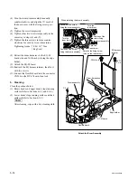
SRW-5000/5500
PSW3
x
8
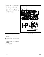
Harness
Harness
CTL/FE head
assembly
Full-erase head
CTL head
Slotted
hole B
Boss
Boss
Boss
(brings near
by the left)
• Top view
Slotted
hole A
Remove/Attach the CTL/FE Head Assembly
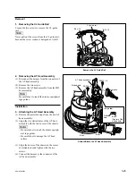
Removal
1. Removing the CTL/FE Head Assembly
(1) Disconnect the two harnesses from the
connectors of the CTL/FE head assembly.
(2) Remove the one screw.
(3) Remove the CTL/FE head assembly from the
MD base assembly.
n
Be careful not to touch the drum or peripheral
tape guides.
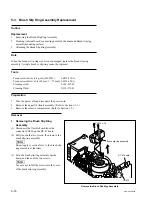
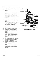
Installation
2. Attaching the CTL/FE Head Assembly
(1) Peel off the protection tape from the new
CTL/FE head assembly.
(2) Confirm that the threading ring is in the
unthreading end state.
(3) Put the slotted holes A and B of the CTL/FE
head assembly into the bosses of the chassis.
n
Be careful not to touch the drum or peripheral
tape guides.
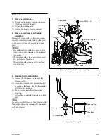
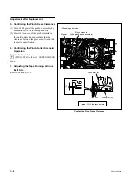
(4) Place the boss of the chassis in the left side of
the slotted hole A and tighten the screw.
(5) Connect the two harnesses to the connectors
of CTL/FE head assembly.
3. Cleaning
Clean the tape-running surfaces of the CTL head
and the full-erase head using a cleaning cloth
moistened with cleaning fluid.
(Refer to Section 4-2-5.)
Adjustment after Replacement
4. Adjusting the Tape Running
Refer to Sections 6-2 to 6-11.
5. Confirming the Tape Running
Refer to Section 6-12.
6. Adjusting the Drum Phase
Refer to Section 7-2-3.
7. Full Erasure Current Check
Refer to Section 8-8-4.
Содержание SRW-5000
Страница 4: ......
Страница 12: ......
Страница 16: ......
Страница 58: ...1 42 SRW 5000 5500 d l l S G L 6 6 d d 4 8 3 7 2 6 0 1 5 9 ...
Страница 78: ......
Страница 194: ......
Страница 376: ......
Страница 398: ......
Страница 438: ...Printed in Japan Sony Corporation 2005 2 08 B P Company 2004 SRW 5000 SY SRW 5500 SY E 9 968 022 03 ...