


6-24
SRW-5000/5500
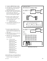
6-6. CTL Head Position Check and Adjustment
Precaution
The CTL head position adjustment is closely related to the AT head position adjust-
ment.
Be sure to confirm the AT head position after adjusting the CTL head position.
Tools
.
Alignment tape HR2-1B:
8-960-076-41
.
Oscilloscope (Tektronix TDS3054B or equivalent)
Preparation
Preparation
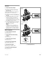
1. Set the Alignment Tape
(1) Turn off the power.
(2) Set the alignment tape HR2-1B and put a
weight (about 1 kg) onto it.
(3) Turn on the power.
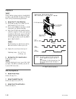
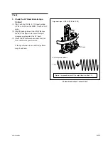
2. Connect the Oscilloscope
Connect the oscilloscope as follows:
CH-1:
TP35/EQ-94 board
(REC CG ENV signal)
CH-2:
TP11/EQ-94 board
(SWP11 signal)
TRIG:
TP200/SS-95 board (SV REF signal)
Oscilloscope setting:
CH-1:
200 to 300 mV/DIV
CH-2:
5 V/DIV
TRIG:
5 V/DIV
TIME:
2 ms/DIV
CH-1: TP35/EQ-94 board (REC CG ENV signal)
CH-2: TP11/EQ-94 board (SWP11 signal)
TRIG: TP200/SS-95 board (SV REF signal)
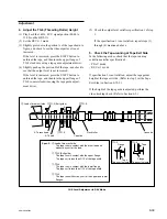
.
Connection of the oscilloscope
<SS-95 board, side A>
<EQ-94 board, side A>
A
B
C
D
E
F
G
H
J
TP35
TP11
K
L
M
N
P
1
2
A
B
C
D
E
F
G
H
J
K
L
M
N
P
1
TP200
Содержание SRW-5000
Страница 4: ......
Страница 12: ......
Страница 16: ......
Страница 58: ...1 42 SRW 5000 5500 d l l S G L 6 6 d d 4 8 3 7 2 6 0 1 5 9 ...
Страница 78: ......
Страница 194: ......
Страница 376: ......
Страница 398: ......
Страница 438: ...Printed in Japan Sony Corporation 2005 2 08 B P Company 2004 SRW 5000 SY SRW 5500 SY E 9 968 022 03 ...