


6-25
SRW-5000/5500
Check
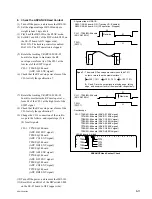
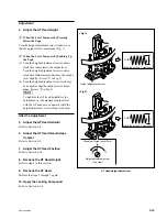
3. Check the CTL Head Position
(1) Play back the HR2-1B (00:00 to 20:00) in the
PLAY mode.
(2) Check that the RF envelope waveform with
the marker shown in the figure appears at the
high level of the SV REF signal and low level
of the SWP11 signal. (Specification 1)
n
The RF envelope waveform is recorded on
HR2-1B (00:00 to 20:00) only for C ch.
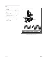
(3) Set Bit-1 of the DIP switch S802 on the SS-
95 board to ON (upper side) to enable the
manual tracking control.
(4) Rotate the tracking VR (RV1001/SS-95
board) until the output level at the center of
the RF envelope with the marker confirmed
in step (2) becomes maximum, and read the
level (L
V
) at that time.
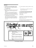
(5) Set Bit-1 and Bit-2 of the DIP switch S802 on
the SS-95 board to OFF (lower side) and ON
(upper side) respectively to fix the tracking
control.
Bit-1: OFF (lower side)
Bit-2: ON (upper side)
(6) Read the output level (L
F
) at the center of the
RF envelope waveform.
(7) Check that the level (L
V
) read at step (4) and
the level (L
F
) read at step (6) satisfy specifi-
cation 2.
If they does not satisfy the specifications 1
and 2, perform step 4 and later.
CTL Head Position Check
L
V
L
F
S802-1/SS-95 board : ON
(Tracking control : Enabled)
.
Alignment tape : HR2-1B (00:00 to 20:00)
S802-1/SS-95 board : OFF (Tracking VR : Disabled)
CH-1
(REC CG ENV)
CH-2
(SWP11)
TRIG
(SV REF)
S802-1/SS-95 board : OFF
(Tracking control : Disabled)
L
F
L
V
>
0.8
H
H
L
H
L
H
L
H
L
H
H
L
L
Marker
A
B
C
D
E
F
G
H
J
K
L
M
N
S802
RV1001 (Tracking VR)
P
1
2
<SS-95 board, side A>
Spec.2 : When the tracking VR is disabled, the output level at
the center portion of the RF envelope waveform (L
F
) is
80 % or more against the maximum output level (L
V
)
under the enabling state of the tracking control.
Spec.1 : The RF envelope waveform with the maker should
appear at the high level of the SV REF signal and
low level of the SWP11 signal.
Содержание SRW-5000
Страница 4: ......
Страница 12: ......
Страница 16: ......
Страница 58: ...1 42 SRW 5000 5500 d l l S G L 6 6 d d 4 8 3 7 2 6 0 1 5 9 ...
Страница 78: ......
Страница 194: ......
Страница 376: ......
Страница 398: ......
Страница 438: ...Printed in Japan Sony Corporation 2005 2 08 B P Company 2004 SRW 5000 SY SRW 5500 SY E 9 968 022 03 ...