


6-36
SRW-5000/5500
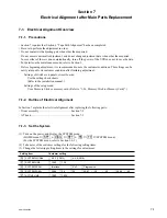
CL guide rail
B3
x
8
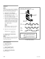
CL Guide Rail Removal/Reattachment
AT Head Position Check
Check
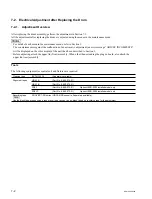
3. Check the AT Head Position
(1) Play back the alignment tape HR2-1B (00:00
to 20:00) in the PLAY mode.
(2) Check that the positional relationship be-
tween the rising edges of CTL’s 65:35 pulse
and TC PB’s 65:35 waveform signals
satisfies the specification.
If the specification is not satisfied, perform steps
4 and later.
n
The TC signal is in 0.15 ms advance of the CTL
signal.
Adjustment
4. Remove the CL Guide Rail
(1) Turn off the power.
(2) Fully loosen the two screws, then remove the
CL guide rail.
.
Alignment tape : HR2-1B (00:00 to 20:00)
CTL PULSE
TC PB
A
65
35
50
50
65
35
Spec. : A = 0.15
±
0.40 ms
Содержание SRW-5000
Страница 4: ......
Страница 12: ......
Страница 16: ......
Страница 58: ...1 42 SRW 5000 5500 d l l S G L 6 6 d d 4 8 3 7 2 6 0 1 5 9 ...
Страница 78: ......
Страница 194: ......
Страница 376: ......
Страница 398: ......
Страница 438: ...Printed in Japan Sony Corporation 2005 2 08 B P Company 2004 SRW 5000 SY SRW 5500 SY E 9 968 022 03 ...