


8-26
SRW-5000/5500
1
2
3
4
5
6
A
B
C
D
E
F
RV500
RV100
RV203
RV103
RV702
RV700
RV703
RV701
TP100
RV202
RV201
RV200
RV205
RV204
TP202
TP201
TP401
TP400
RV401
E600
TP601
RV400
TP300
RV300
TP200
TP500
E100
RV101 RV102
S100
LV400
LV600
T500
E500
S200
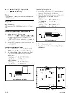
8. CUE REC Level Adjustment
1.
Input the audio signal 1 kHz
+
4 dBu to CUE INPUT
connector of the connector panel.
2.
Connect the audio analyzer to CUE OUT connector of
the connector panel.
3.
Set the audio analyzer as follows:
Measuring mode: LEVEL, dBu
Input filter:
80 kHz LPF
4.
Insert the recording tape, then perform recording and
playback.
5.
Check the PB level using audio analyzer.
If the audio level is not within the specification, adjust
it in the REC mode, then check it in the PB mode
again. Repeat till the level is within the specification.
Adjusting point (REC mode):
1
RV400/AE-31H (B-5)
Specification (PB mode):
+
4.0
±
0.2 dBu
9. CUE REC Frequency Response Adjustment
1.
Connect the audio analyzer to CUE OUT connector of
the connector panel.
2.
Set the audio analyzer as follows:
Measuring mode: LEVEL, dBu
Input filter:
80 kHz LPF
3.
Insert the recording tape.
4.
Input the audio signal
_
16 dBu to CUE INPUT
connector of the connector panel, and then record the
following frequency sequentially.
Recording audio signal:
_
16 dBu
1 kHz, 3 kHz, 7 kHz,
10 kHz, and 12 kHz
5.
Play back the recorded portion, and then check the
level for each frequency using the audio analyzer. If
the level is not within the specification, adjust it in the
REC mode while checking the level in the PB mode.
Firstly adjust the level of 10 kHz until it equates with
the level of 1 kHz. Then, check each of other frequen-
cy alike.
Adjusting point (REC mode):
1
RV401/AE-31H (C-5)
Specification (PB mode):
Each frequency level
1 kHz level
±
0.9 dB
5. CUE Bias Frequency Adjustment
1.
Connect the frequency counter to TP500/AE-31H (F-
3).
GND: E500/AE-31H (F-4)
2.
Insert the recording tape to have the VTR in the
recording mode.
3.
Check the frequency using the frequency counter, and
then adjust it.
Adjusting point:
1
T500/AE-31H (F-3)
Specification:
160
±
10 kHz
6. CUE Bias Trap Adjustment
1.
Disconnect a cable to the CUE INPUT connector of
the connector panel if it is connected.
2.
Connect the oscilloscope to TP401/AE-31H (E-4).
GND: E500/AE-31H (F-4)
3.
Insert the recording tape to have the VTR in the
recording mode.
4.
Check the level using the audio level meter, and then
adjust it.
Adjusting point:
1
LV400/AE-31H (E-4)
Specification:
Minimize
7. CUE Bias Current Adjustment
1.
Ensure that nothing is connected to the CUE INPUT
connector.
2.
Connect the audio level meter to TP200/AE-31H (E-
3).
GND: TP201/AE-31H (E-3)
3.
Insert the recording tape to have the VTR in the
recording mode.
4.
Check the level using the audio level meter, and then
adjust it.
Adjusting point:
1
RV500/AE-31H (F-1)
Specification:
16
±
0.5 mVrms
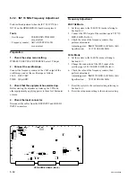
AE-31H Board (Side A)
Содержание SRW-5000
Страница 4: ......
Страница 12: ......
Страница 16: ......
Страница 58: ...1 42 SRW 5000 5500 d l l S G L 6 6 d d 4 8 3 7 2 6 0 1 5 9 ...
Страница 78: ......
Страница 194: ......
Страница 376: ......
Страница 398: ......
Страница 438: ...Printed in Japan Sony Corporation 2005 2 08 B P Company 2004 SRW 5000 SY SRW 5500 SY E 9 968 022 03 ...