


5-13
SRW-5000/5500
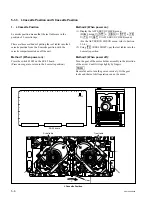
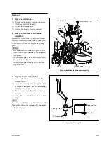
Drum assembly
Positioning hole
Edge holder
Positioning
hole
Drum
harness(20P)
Positioning pins
Drum harness
(22P)
Drum
support
Pulling up the drum
harnesses.
Drum
harness(30P)
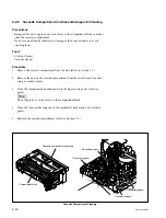
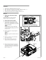
4. Attaching the Drum Assembly
(1) Hold the drum assembly as shown in the
figure and connect the three drum harnesses
disconnected in (7) of step 2 to the connec-
tors of drum assembly.
m
.
Hold the drum support, not to hold the upper
drum portion and the brush slip ring assem-
bly.
.
Pay attention to the orientation of the
connectors.
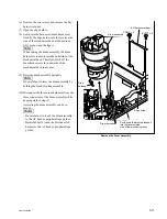
(2) Align the two positioning holes of the drum
assembly with the two positioning pins of the
MD base assembly while pulling up the three
drum harnesses shown in the figure.
m
.
Avoid pulling the three drum harnesses
forcibly, or the harnesses may come off the
drum assembly.
.
Be careful not to touch the drum assembly
to the AT head or peripheral tape guides at
that time.
.
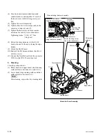
Be careful not to put the harnesses between
the drum motor portion and the MD base
assembly.
(3) Confirm that the drum assembly is firmly
inserted into the positioning pins.
Содержание SRW-5000
Страница 4: ......
Страница 12: ......
Страница 16: ......
Страница 58: ...1 42 SRW 5000 5500 d l l S G L 6 6 d d 4 8 3 7 2 6 0 1 5 9 ...
Страница 78: ......
Страница 194: ......
Страница 376: ......
Страница 398: ......
Страница 438: ...Printed in Japan Sony Corporation 2005 2 08 B P Company 2004 SRW 5000 SY SRW 5500 SY E 9 968 022 03 ...