


6-6
SRW-5000/5500
A
B
C
D
E
F
G
H
J
K
L
M
N
P
1
2
TP52
TP5
A
B
C
D
E
F
G
H
J
K
L
M
N
P
1
2
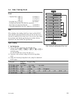
S1002
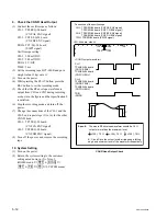
<EQ-94 board, side A>
CH-1 : TP52/EQ-94 board (CNF CG ENV signal)
CH-2 : TP5/EQ-94 board (SWP5 signal)
TRIG : CH-2
<SS-95 board, side A>
.
Connection of the oscilloscope
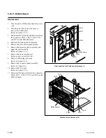
Preparation
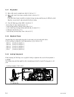
Setting
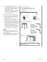
2. Set the Alignment Tape
(1) Press the switch S1002 on the SS-95 board
during power-on to set the reel tables to the S
cassette position.
(Refer to Section 5-1-3.)
(2) Turn off the power.
(3) Set the alignment tape HR2-1B and put a
weight (about 1 kg) onto it.
3. Connect the Oscilloscope
Connect the oscilloscope as follows:
CH-1: TP52/EQ-94 board (CNF CG ENV signal)
CH-2: TP5/EQ-94 board (SWP5 signal)
TRIG: Set CH-2 as TRIG input.
Oscilloscope setting:
CH-1: 100 mV to 200 mV/DIV
CH-2: 5 V/DIV
TIME: 0.5 to 1 ms/DIV
Содержание SRW-5000
Страница 4: ......
Страница 12: ......
Страница 16: ......
Страница 58: ...1 42 SRW 5000 5500 d l l S G L 6 6 d d 4 8 3 7 2 6 0 1 5 9 ...
Страница 78: ......
Страница 194: ......
Страница 376: ......
Страница 398: ......
Страница 438: ...Printed in Japan Sony Corporation 2005 2 08 B P Company 2004 SRW 5000 SY SRW 5500 SY E 9 968 022 03 ...