


6-2
SRW-5000/5500
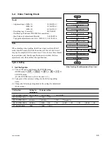
TG-0
TG-6
TG-4
Slant guide
CTL head
TG-2
Full-erase head
(Recorder only)
Tape cleaner
TG-5 (Threading roller)
TG-1
(S tension regulator)
Capstan
Pinch roller
AT head
AT erase head
TG-3 (Exit guide)
TG-10
TG-9
TG-8
(T tension regulator)
TG-7
Drum
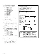
6-1-3. Parts Location of the Tape Path System
Following figure describes the names of each part of the tape path system.
It is illustrated in the threading end mode of the recorder. “ TG ” in the figure means
the tape guide.
6-1-4. Cassette Compartment
(1) The tape path adjustment should be performed under the state that the cassette
compartment is removed. If not, some checks and adjustments may be impossi-
ble.
(2) When the tape path adjustment is performed with the cassette compartment
removed, the tape protection circuit is activated and the “ERROR” message may
be displayed. In this case, turn the power off, then turn it on again.
Содержание SRW-5000
Страница 4: ......
Страница 12: ......
Страница 16: ......
Страница 58: ...1 42 SRW 5000 5500 d l l S G L 6 6 d d 4 8 3 7 2 6 0 1 5 9 ...
Страница 78: ......
Страница 194: ......
Страница 376: ......
Страница 398: ......
Страница 438: ...Printed in Japan Sony Corporation 2005 2 08 B P Company 2004 SRW 5000 SY SRW 5500 SY E 9 968 022 03 ...