Installation
UMSITRPDS3-1
November
2010
4-32
8.
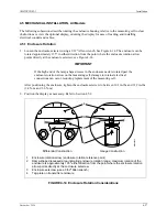
Ground the enclosure by installing a 16 AWG (1.3 mm
2
) or larger copper wire between the enclosure
ground screw and a low resistance ground, such as a nearby metal cold water pipe.
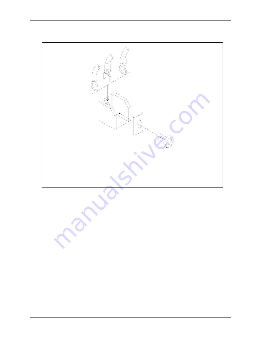
1
2
3
4
5
6
MG
00355a
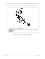
1. Solid conductor with loop formed in end of lead
2. Stranded conductor with spring spade terminal
3. Stranded conductor with ring tongue terminal
4. One of three terminals in the electrical enclosure. Remove end cap to access terminals.
5. Terminal screw
6. Pressure plate
FIGURE 4-17 Network Conductor Terminations
Содержание 7MF4033 series
Страница 48: ...Model 275 Universal Hart Communicator UMSITRPDS3 1 November 2010 2 26 ...
Страница 86: ...Installation UMSITRPDS3 1 November 2010 4 34 ...
Страница 152: ...Calibration and Maintenance UMSITRPSD3 1 November 2010 7 20 ...
Страница 158: ...Circuit Description UMSITRPDS3 1 November 2010 8 6 ...
Страница 197: ......
Страница 198: ......
Страница 200: ...Model Designations and Specifications UMSITRPDS3 1 November 2010 9 42 ...
Страница 204: ...Glossary UMSITRPDS3 1 November 2010 10 4 ...
Страница 208: ...Appendix A Online Configuration Map UMSITRPDS3 1 11 4 November 2010 ...
Страница 210: ...Appendix B Hazardous Area Installation UMSITRPDS3 1 12 2 November 2010 FIGURE 12 1 Control Drawing ...
Страница 211: ...UMSITRPDS3 1 Appendix B Hazardous Area Installation November 2010 12 3 FIGURE 12 2 Control Drawing ...
Страница 212: ...Appendix B Hazardous Area Installation UMSITRPDS3 1 12 4 November 2010 FIGURE 12 3 Control Drawing ...
Страница 216: ...Appendix C Elevation and Suppression Correction UMSITRPDS3 1 13 4 November 2010 ...


