Calibration and Maintenance
UMSITRPSD3-1
November
2010
7-6
Transmitter Troubleshooting Steps
Several troubleshooting avenues are presented below. Select the appropriate path for the encountered
symptoms.
•
Record the readings in the numeric display, status arrows, and sign. Note the reading(s) in the
unit/bargraph display, particularly any static or scrolling message. The display is discussed in Section
6 On-Line Calibration and Operation.
•
If the display is blank or partial characters appear, connect the HART Communicator in the loop.
If the Communicator shows correct data, replace the display. If the problem remains, replace the
electronics module. If the Communicator does not show correct data, use a voltmeter to confirm
that power is applied to the transmitter. If power is applied, replace the electronics module.
•
ERROR appears on the display – There is a hardware or software malfunction. Replace the
electronics module. If the problem remains, replace the measuring cell.
•
A static or scrolling message appears in the unit/bargraph display - This is a notice of a
malfunction or a change in a status, warning, or alarm. Read the message and respond
accordingly. Check the transmitter configuration and process conditions.
•
Warning/Alarm indication - Check the configuration of: Calibrate interval, Service interval, and
AO saturation. The warning/alarm may be an indication that a configured time has elapsed or that
the analog output has saturated. Check transmitter configuration and process conditions.
•
Perform a transmitter self test or reset. Refer to Section 6.4.21 Self Test and Master Reset. Again
check data and messages and repair as indicated.
Initially the numeric display will momentarily show “Init” and then display the current output (unless
the display is set to read another parameter or ERROR appears). The unit/bargraph display will show
the engineering unit (unless a fixed message or scrolling message appears or the unit/bargraph display
is set to the bargraph mode). If a failed test message appears, repair as necessary.
•
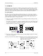
Check the pressure to current conversion. Connect a pressure source to the transmitter and connect
the HART Communicator in the loop. Set the pressure source to produce a 4 mA transmitter output
current. In the Online menu, press 3 Device Setup and then press 1 Process Variables to observe the
active data. Refer to Appendix A Online Configuration Map as needed. Change the pressure to
produce a 20 mA output current.
If a display is not installed, a milliammeter can be connected after removing the enclosure cap for
access to the 4-20 mA test terminals.
•
Place the transmitter in the simulation mode to apply a fixed or ramping current to the loop. Refer to
Section 6.4.20 Simulation. Troubleshoot the controller or device receiving the transmitter output
signal. Check the loop wiring at all loop-connected devices.
If selected loop currents are significantly out of tolerance, or loop current cannot be set, replace the
electronics module (see Section 7.4). If the transmitter passes the fixed current (loop override) test,
continue troubleshooting.
DSIII electronic modules are interchangeable. If troubleshooting points to a failed display or electronics
module, substitute a known good assembly for another transmitter or from spare parts stock. See Section
7.4 for assembly replacement steps. Replacing the electronics module will necessitate reconfiguration of
the transmitter since configuration data are stored in the module.
Содержание 7MF4033 series
Страница 48: ...Model 275 Universal Hart Communicator UMSITRPDS3 1 November 2010 2 26 ...
Страница 86: ...Installation UMSITRPDS3 1 November 2010 4 34 ...
Страница 152: ...Calibration and Maintenance UMSITRPSD3 1 November 2010 7 20 ...
Страница 158: ...Circuit Description UMSITRPDS3 1 November 2010 8 6 ...
Страница 197: ......
Страница 198: ......
Страница 200: ...Model Designations and Specifications UMSITRPDS3 1 November 2010 9 42 ...
Страница 204: ...Glossary UMSITRPDS3 1 November 2010 10 4 ...
Страница 208: ...Appendix A Online Configuration Map UMSITRPDS3 1 11 4 November 2010 ...
Страница 210: ...Appendix B Hazardous Area Installation UMSITRPDS3 1 12 2 November 2010 FIGURE 12 1 Control Drawing ...
Страница 211: ...UMSITRPDS3 1 Appendix B Hazardous Area Installation November 2010 12 3 FIGURE 12 2 Control Drawing ...
Страница 212: ...Appendix B Hazardous Area Installation UMSITRPDS3 1 12 4 November 2010 FIGURE 12 3 Control Drawing ...
Страница 216: ...Appendix C Elevation and Suppression Correction UMSITRPDS3 1 13 4 November 2010 ...


