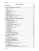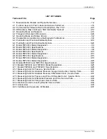
Contents
UMSITRPDS3-1
November
2010
viii
Conventions, Symbols, and General Information
Conventions and Symbols
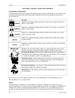
The following symbols may be used in this manual and may appear on the equipment. The reader should
be familiar with the symbols and their meanings. Symbols are provided to quickly alert the reader to
safety related text.
Symbol Meaning
DANGER
Indicates an immediate hazardous situation which, if not avoided,
will
result in
death or serious injury.
WARNING
Indicates a potentially hazardous situation which, if not avoided,
could
result in
death or serious injury.
CAUTION
Indicates a potentially hazardous situation which, if not avoided,
may
result in
minor or moderate injury.
CAUTION
Indicates a potentially hazardous situation which, if not avoided, may result in
property damage.
NOTICE
Indicates a potential situation which, if not avoided, may result in an undesirable
result or state.
IMPORTANT
Identifies an action that should be taken to avoid an undesirable result or state.
Note
Identifies supplemental information that should be read before proceeding.
Electrical shock hazard –
Either symbol indicates the presence of an electrical
shock hazard. The associated text states the nature of the hazard, what can happen
as a result of the hazard, and how to avoid the hazard..
Explosion hazard –
Symbol indicates that the danger of an explosion hazard
exists. The associated text states the nature of the hazard, what can happen as a
result of the hazard, and how to avoid the hazard.
Electrostatic discharge –
The presence of this symbol indicates that electrostatic
discharge can damage the electronic assembly.
Pinch hazard –
Symbol indicates that a pinch hazard exists if correct procedures
are not followed.
Part numbers are for items ordered from the Process Instrumentation & Analytics Business Unit of
Siemens Industry, Inc., except as noted.
Scope
This manual does not purport to cover all details or variations in equipment or to provide for every
possible contingency to be met in connection with installation, operation, or maintenance. Should further
information be desired or should particular problems arise which are not covered sufficiently for the
purchaser’s purposes, the matter should be referred to a support group listed in the Customer/Product
Содержание 7MF4033 series
Страница 48: ...Model 275 Universal Hart Communicator UMSITRPDS3 1 November 2010 2 26 ...
Страница 86: ...Installation UMSITRPDS3 1 November 2010 4 34 ...
Страница 152: ...Calibration and Maintenance UMSITRPSD3 1 November 2010 7 20 ...
Страница 158: ...Circuit Description UMSITRPDS3 1 November 2010 8 6 ...
Страница 197: ......
Страница 198: ......
Страница 200: ...Model Designations and Specifications UMSITRPDS3 1 November 2010 9 42 ...
Страница 204: ...Glossary UMSITRPDS3 1 November 2010 10 4 ...
Страница 208: ...Appendix A Online Configuration Map UMSITRPDS3 1 11 4 November 2010 ...
Страница 210: ...Appendix B Hazardous Area Installation UMSITRPDS3 1 12 2 November 2010 FIGURE 12 1 Control Drawing ...
Страница 211: ...UMSITRPDS3 1 Appendix B Hazardous Area Installation November 2010 12 3 FIGURE 12 2 Control Drawing ...
Страница 212: ...Appendix B Hazardous Area Installation UMSITRPDS3 1 12 4 November 2010 FIGURE 12 3 Control Drawing ...
Страница 216: ...Appendix C Elevation and Suppression Correction UMSITRPDS3 1 13 4 November 2010 ...


