UMSITRPDS3-1
Installation
November 2010
4-29
4.5.3 Electrical Conduit and Cable Installation
All electrical conduit and all signal wires must be supplied by the user. Access to electrical terminals is
described in Section 4.5.2.3.
For conduit and cable routing, refer to user’s installation drawings. Installation of conduit and cabling
should follow the guidelines given below.
4.5.3.1 Conduit
•
Transmitter conduit inlets accept male conduit fittings. Refer to the transmitter’s rating plate and
Section 9.1 to determine whether conduit threads are 1/2-14 NPT or M20 x 1.5.
Seal NPT fittings with Teflon tape; seal M20 fittings with a soft-setting sealing compound rated for at
least 105°C (221°F).
•
When routing conduit, avoid areas that might subject the conduit to chemical or physical abuse or
areas with high electromagnetic interference/radio frequency interference (EMI/RFI) conditions.
•
Install conduit for field wiring.
•
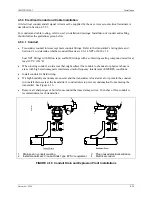
If a high humidity environment can exist and the transmitter is located at a low point in the conduit
run, install drain seals at the transmitter’s conduit inlets to prevent condensation from entering the
transmitter. See Figure 4-16.
•
Remove all sharp edges or burrs from conduit that may damage wires; 18-inches of flex conduit is
recommended at each transmitter.
MG
0035
4a
Conduit Drain
Explosion Proof
+
+
+
+
+
+
+
+
1
2
3
3
4
4
1
2
Drain seal in conduit coupling
Install conduit seal: Crouse-Hinds Type EYS or equivalent
3
4
Plug unused electrical entrance
Electrical conduit
FIGURE 4-16 Conduit Drain and Explosion Proof Installations
Содержание 7MF4033 series
Страница 48: ...Model 275 Universal Hart Communicator UMSITRPDS3 1 November 2010 2 26 ...
Страница 86: ...Installation UMSITRPDS3 1 November 2010 4 34 ...
Страница 152: ...Calibration and Maintenance UMSITRPSD3 1 November 2010 7 20 ...
Страница 158: ...Circuit Description UMSITRPDS3 1 November 2010 8 6 ...
Страница 197: ......
Страница 198: ......
Страница 200: ...Model Designations and Specifications UMSITRPDS3 1 November 2010 9 42 ...
Страница 204: ...Glossary UMSITRPDS3 1 November 2010 10 4 ...
Страница 208: ...Appendix A Online Configuration Map UMSITRPDS3 1 11 4 November 2010 ...
Страница 210: ...Appendix B Hazardous Area Installation UMSITRPDS3 1 12 2 November 2010 FIGURE 12 1 Control Drawing ...
Страница 211: ...UMSITRPDS3 1 Appendix B Hazardous Area Installation November 2010 12 3 FIGURE 12 2 Control Drawing ...
Страница 212: ...Appendix B Hazardous Area Installation UMSITRPDS3 1 12 4 November 2010 FIGURE 12 3 Control Drawing ...
Страница 216: ...Appendix C Elevation and Suppression Correction UMSITRPDS3 1 13 4 November 2010 ...


