On-Line Operation
UMSITRPDS3-1
November
2010
6-10
Adjust Zero and Full Scale
If only a single reference pressure is available, calculate the currents to be adjusted using the formulas and
procedure in Section 6.2.2.1 subsection Adjusting Zero and Full Scale from a Single Reference.
1.
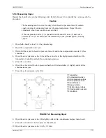
If the transmitter does not have a display and an external milliammeter must be connected to read
analog output current, remove the field terminals enclosure cap and connect the milliammeter.
WARNING
Explosion can cause death or serious injury.
Only a certified ammeter may be used in intrinsically
safe circuits.
In a Division 1 area, where an explosion-proof rating is
required, remove power from the transmitter before
removing either enclosure cap.
2.
Apply a known reference pressure.
3.
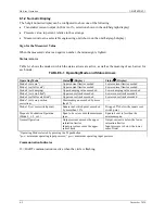
Press the M pushbutton until mode 2 appears.
4.
Set zero by pressing the
(
or
'
pushbutton.
5.
Press the M pushbutton to save the setting and go to mode 3.
6.
Set full scale by pressing the
(
or
'
pushbutton.
7.
Press the M pushbutton to save the setting.
6.2.3 Electric Damping
Set the electronic damping time constant to between 0-100 seconds, in steps of 0.1 seconds, using the
magnetic pushbuttons.
1.
Press the M pushbutton until mode 4 appears.
2.
Press the
(
or
'
pushbutton to set the damping to the desired value.
3.
Save the setting by pressing the M pushbutton.
6.2.4 Blind Setting of Zero and Full Scale
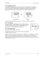
Modes 5 and 6 are used to set or adjust zero and full scale respectively with no input pressure applied to
the transmitter. It is also possible to change between forward acting and reverse acting characteristics
here.
6.2.4.1 Theoretical Relationships
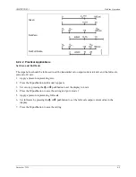
To adjust zero and full scale:
1.
Select the desired engineering unit.
2.
Select mode 5 and press and press the
(
or
'
pushbutton to adjust the lower pressure value that is to
be equivalent to a 4 mA output. (Note that the pressure adjustment will not go below zero even if the
lower sensor limit (LSL) is below zero.)
3.
Select mode 6 and press the
(
or
'
pushbutton adjust the upper pressure value that is to be
equivalent to a 20 mA output. (The assumed pressure will be the upper sensor limit.)
Содержание 7MF4033 series
Страница 48: ...Model 275 Universal Hart Communicator UMSITRPDS3 1 November 2010 2 26 ...
Страница 86: ...Installation UMSITRPDS3 1 November 2010 4 34 ...
Страница 152: ...Calibration and Maintenance UMSITRPSD3 1 November 2010 7 20 ...
Страница 158: ...Circuit Description UMSITRPDS3 1 November 2010 8 6 ...
Страница 197: ......
Страница 198: ......
Страница 200: ...Model Designations and Specifications UMSITRPDS3 1 November 2010 9 42 ...
Страница 204: ...Glossary UMSITRPDS3 1 November 2010 10 4 ...
Страница 208: ...Appendix A Online Configuration Map UMSITRPDS3 1 11 4 November 2010 ...
Страница 210: ...Appendix B Hazardous Area Installation UMSITRPDS3 1 12 2 November 2010 FIGURE 12 1 Control Drawing ...
Страница 211: ...UMSITRPDS3 1 Appendix B Hazardous Area Installation November 2010 12 3 FIGURE 12 2 Control Drawing ...
Страница 212: ...Appendix B Hazardous Area Installation UMSITRPDS3 1 12 4 November 2010 FIGURE 12 3 Control Drawing ...
Страница 216: ...Appendix C Elevation and Suppression Correction UMSITRPDS3 1 13 4 November 2010 ...


