IMPORTANT
MODEL 275 HART COMMUNICATOR AND
MODEL 375 FIELD COMMUNICATOR
Many procedures, screens, and wiring diagrams shown in this manual feature the Model 275 HART
Communicator.
The Model 375 Field Communicator is also available. Procedures and screens are similar to those for the
Model 275, however, there are significant differences and an online Configuration Map for use with the
Model 375 is provided at the back of this manual.
Transmitter model and firmware version can affect the displays, display options, and Configuration Maps.
Whether using the Model 275 or the Model 375, be sure to read the manual supplied by the manufacturer
before installing or using the device. Refer to the communicator nameplate for hazardous area
certifications and approvals and other important information.
APPLICATION AND MODEL QUICK LOCATOR
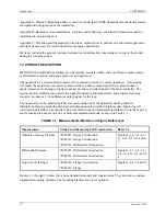
The following table provides an overview of measurement categories and available models. For details
pertaining to a particular model, see the appropriate section for a dimension drawing, the model
designation table and specifications in Section 9 Model Designations and Specifications. To quickly
locate other information, refer to the Table of Contents.
Measurement Models
See
Section
Dimensions
Model
Designation
Specifications
Absolute or Gauge
Pressure
7MF4033
7MF4233
7MF4333
9.1
9.2
9.3
Figure 9-1
Figure 9-2
Figure 9-3
Table 9-1
Table 9-3
Table 9-5
Table 9-2
Table 9-4
Table 9-6
Differential
Pressure
7MF4433
7MF4533
9.4
Figure 9-3 or 9-4
Table 9-7
Table 9-8
Table 9-9
Level (Flange)
7MF4633
7MF4812
9.5
Figure 9-5
Table 9-10
Table 9-11
Содержание 7MF4033 series
Страница 48: ...Model 275 Universal Hart Communicator UMSITRPDS3 1 November 2010 2 26 ...
Страница 86: ...Installation UMSITRPDS3 1 November 2010 4 34 ...
Страница 152: ...Calibration and Maintenance UMSITRPSD3 1 November 2010 7 20 ...
Страница 158: ...Circuit Description UMSITRPDS3 1 November 2010 8 6 ...
Страница 197: ......
Страница 198: ......
Страница 200: ...Model Designations and Specifications UMSITRPDS3 1 November 2010 9 42 ...
Страница 204: ...Glossary UMSITRPDS3 1 November 2010 10 4 ...
Страница 208: ...Appendix A Online Configuration Map UMSITRPDS3 1 11 4 November 2010 ...
Страница 210: ...Appendix B Hazardous Area Installation UMSITRPDS3 1 12 2 November 2010 FIGURE 12 1 Control Drawing ...
Страница 211: ...UMSITRPDS3 1 Appendix B Hazardous Area Installation November 2010 12 3 FIGURE 12 2 Control Drawing ...
Страница 212: ...Appendix B Hazardous Area Installation UMSITRPDS3 1 12 4 November 2010 FIGURE 12 3 Control Drawing ...
Страница 216: ...Appendix C Elevation and Suppression Correction UMSITRPDS3 1 13 4 November 2010 ...


