On-Line Operation
UMSITRPDS3-1
November
2010
6-4
1
2
3
4
5
6
7
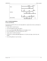
Linear modulation range
Lower limit of the modulation range (default value)
Upper limit of the modulation range (default value)
Lower fault current value (default value)
Upper fault current value (default value)
Recommended setting range for lower fault current range and lower modulation range limit
Recommended setting range for upper fault current range and upper modulation range limit
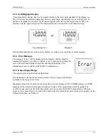
6.1.6 Mode Display
An operating mode is selected by pressing the M pushbutton. The selected
mode is shown in the lower left quadrant of the digital display. In the
example at right, mode 4 Electric Damping has been selected and a
damping value of 0.2 has been set.
Содержание 7MF4033 series
Страница 48: ...Model 275 Universal Hart Communicator UMSITRPDS3 1 November 2010 2 26 ...
Страница 86: ...Installation UMSITRPDS3 1 November 2010 4 34 ...
Страница 152: ...Calibration and Maintenance UMSITRPSD3 1 November 2010 7 20 ...
Страница 158: ...Circuit Description UMSITRPDS3 1 November 2010 8 6 ...
Страница 197: ......
Страница 198: ......
Страница 200: ...Model Designations and Specifications UMSITRPDS3 1 November 2010 9 42 ...
Страница 204: ...Glossary UMSITRPDS3 1 November 2010 10 4 ...
Страница 208: ...Appendix A Online Configuration Map UMSITRPDS3 1 11 4 November 2010 ...
Страница 210: ...Appendix B Hazardous Area Installation UMSITRPDS3 1 12 2 November 2010 FIGURE 12 1 Control Drawing ...
Страница 211: ...UMSITRPDS3 1 Appendix B Hazardous Area Installation November 2010 12 3 FIGURE 12 2 Control Drawing ...
Страница 212: ...Appendix B Hazardous Area Installation UMSITRPDS3 1 12 4 November 2010 FIGURE 12 3 Control Drawing ...
Страница 216: ...Appendix C Elevation and Suppression Correction UMSITRPDS3 1 13 4 November 2010 ...


