On-Line Operation
UMSITRPDS3-1
November
2010
6-14
6.2.8 Pushbutton and Function Disable
Mode 10 is used to disable some or all magnetic pushbutton functions. In addition, a write protect
function can be activated to prevent changing of saved parameters. There are five options as shown in
Table 6.3.
TABLE 6-3 Pushbutton and Function Disable Options
Symbol Explanation
no symbol
No disable.
LA
Input pushbuttons disabled. Operation via HART is enabled.
LO
Zero can be set; all other functions are disabled. Operation via HART is enabled.
LS
Only zero and full scale can be set (see Section 6.3); all other functions are disabled.
Operation via HART is enabled.
L
Write protect enabled. Operation by HART disabled.
LL is another pushbutton disable that is available in HART; see Section 6.4.9. The disable option symbol
will appear in the lower left quadrant of the digital display. To cancel a disable option, see Section 6.2.1.
To select a pushbutton or function disable option:
1.
If LO or LS is to be selected, first press the M pushbutton to go to mode 13. Select either Current in
mA or Current in %. Otherwise, a change in the output variable will not be detected when an arrow
pushbutton is pressed.
2.
Press the M pushbutton to go the mode 10. Select a disable option by pressing either arrow
pushbutton.
3.
Press the M pushbutton to save the selection.
Note
When a transmitter is delivered without a display, disable option LS is active. If
the transmitter is to be permanently operated without a display, be sure option LS
remains active.
6.2.9 Flow Measurement (Differential Pressure only)
Select the characteristic of the output current as follows:
•
Linear - proportional to the differential pressure
•
Square Root - proportional to the flow
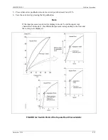
Below the switch point of the square root function, output current can have a linear characteristic (SrLin),
rise slowly to 0.6% and then increase linearly (SrLi2), or stay at 4 mA (SroFF). See Figure 6-2 for the
three characteristics.
To select the characteristics:
1.
Press the M pushbutton to enable mode 11.
2.
Press either arrow pushbutton to select the desired characteristic.
3.
Press the M pushbutton to save the selection.
4.
Press the M pushbutton to enable mode 12.
Содержание 7MF4033 series
Страница 48: ...Model 275 Universal Hart Communicator UMSITRPDS3 1 November 2010 2 26 ...
Страница 86: ...Installation UMSITRPDS3 1 November 2010 4 34 ...
Страница 152: ...Calibration and Maintenance UMSITRPSD3 1 November 2010 7 20 ...
Страница 158: ...Circuit Description UMSITRPDS3 1 November 2010 8 6 ...
Страница 197: ......
Страница 198: ......
Страница 200: ...Model Designations and Specifications UMSITRPDS3 1 November 2010 9 42 ...
Страница 204: ...Glossary UMSITRPDS3 1 November 2010 10 4 ...
Страница 208: ...Appendix A Online Configuration Map UMSITRPDS3 1 11 4 November 2010 ...
Страница 210: ...Appendix B Hazardous Area Installation UMSITRPDS3 1 12 2 November 2010 FIGURE 12 1 Control Drawing ...
Страница 211: ...UMSITRPDS3 1 Appendix B Hazardous Area Installation November 2010 12 3 FIGURE 12 2 Control Drawing ...
Страница 212: ...Appendix B Hazardous Area Installation UMSITRPDS3 1 12 4 November 2010 FIGURE 12 3 Control Drawing ...
Страница 216: ...Appendix C Elevation and Suppression Correction UMSITRPDS3 1 13 4 November 2010 ...


