Calibration and Maintenance
UMSITRPSD3-1
November
2010
7-18
6.
Check all connections, then open shut-off valves and close by-pass valves. As needed, refer to
Section 5 Post Installation Test.
Caution
Do not exceed the Maximum Overrange ratings when placing the transmitter into
service. Properly operate all shut-off and equalizing valves. Ratings are listed on
the rating plate and in Section 9 Model Designation and Specifications.
7.
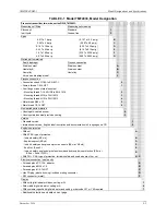
Check transmitter configuration as described in Section 3.4 Reviewing Configuration Data and
Section 6 Online Configuration and Operation.
8.
If needed, perform mounting induced zero shift calibration (see Section 7.1).
7.7 MAINTENANCE RECORDS
An accurate record keeping system for tracking maintenance operations should be established and kept up
to date. Data extracted from the record may serve as a base for ordering maintenance supplies, including
spare parts. The record may also be useful as a troubleshooting tool. In addition, maintenance records
may be required to provide documentary information in association with a service contract. It is suggested
that, as appropriate, the following information be recorded:
1.
Date of service incident
2.
Name or initials of service person
3.
Brief description of incident symptoms and repairs performed
4.
Replacement part or assembly number
5.
Software compatibility code of original part
6.
Software code of replacement part
7.
Serial number of original part
8.
Serial number of replacement part
9.
Issue number of original circuit module
10.
Issue number of replacement circuit module
11.
Date of completion
7.8 RECOMMENDED SPARE AND REPLACEMENT PARTS
The quantity and variety of spare parts is determined by how much time a transmitter can be permitted to
remain out of service or off line.
Replaceable parts are listed in Section 9 Model Designations and Specifications (Tables 9-7 to 9-13).
Contact the factory if assistance is needed in determining quantity and selection of spare parts.
When ordering a part, provide the following information for the item, module or assembly to be replaced
or spared. This information will help ensure that a repair addresses the observed problem, and that a
compatible part is supplied.
1.
Complete part number from Section 9 or from a label on the assembly
2.
The single-digit software revision level
3.
Model and serial number from the transmitter’s nameplate
4.
User purchase order number of original order, available from user records
5.
New user purchase order number for the assembly to be replaced or spared
Содержание 7MF4033 series
Страница 48: ...Model 275 Universal Hart Communicator UMSITRPDS3 1 November 2010 2 26 ...
Страница 86: ...Installation UMSITRPDS3 1 November 2010 4 34 ...
Страница 152: ...Calibration and Maintenance UMSITRPSD3 1 November 2010 7 20 ...
Страница 158: ...Circuit Description UMSITRPDS3 1 November 2010 8 6 ...
Страница 197: ......
Страница 198: ......
Страница 200: ...Model Designations and Specifications UMSITRPDS3 1 November 2010 9 42 ...
Страница 204: ...Glossary UMSITRPDS3 1 November 2010 10 4 ...
Страница 208: ...Appendix A Online Configuration Map UMSITRPDS3 1 11 4 November 2010 ...
Страница 210: ...Appendix B Hazardous Area Installation UMSITRPDS3 1 12 2 November 2010 FIGURE 12 1 Control Drawing ...
Страница 211: ...UMSITRPDS3 1 Appendix B Hazardous Area Installation November 2010 12 3 FIGURE 12 2 Control Drawing ...
Страница 212: ...Appendix B Hazardous Area Installation UMSITRPDS3 1 12 4 November 2010 FIGURE 12 3 Control Drawing ...
Страница 216: ...Appendix C Elevation and Suppression Correction UMSITRPDS3 1 13 4 November 2010 ...


