On-Line Operation
UMSITRPDS3-1
November
2010
6-6
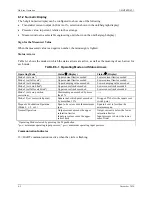
TABLE 6-2 Parameters Accessible Using the Magnetic Pushbuttons
Configuration Mode
Increase/Decrease
Pushbuttons (Keys)
Description
See
Parameter
M
1
(
Increase
'
Decrease
(
and
'
3
Section
Measured value
---
---
---
---
Output current in mA or %
or input pressure in
selected engineering units
6.2.10
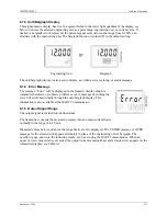
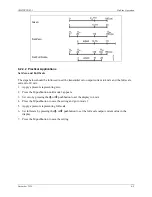
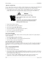
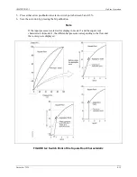
Error
display
---
--- --- ---
Error
6.2.7
Zero
2
Increase current
Decrease current
Set to 4 mA
Output current in mA
6.2.2
Full scale
3
Increase current
Decrease current
Set to 20 mA
Output current in mA
6.2.2
Electric damping
4
Increase damping
Decrease damping ---
Range
0.0
to 100.0 seconds 6.2.3
Zero “blind
setting”
5
Increase pressure
Decrease pressure Set to start of
scale 0
Zero in the selected
engineering unit
6.2.4
Full scale “blind
setting”
6
Increase pressure
Decrease pressure Set to upper
measuring limit
Full scale in the selected
engineering unit
6.2.4
Zero for position
correction
2
7
--- --- Press
both
pushbuttons
simultaneously
Re-zero when oriented
from vertical
6.2.5
Output Current
8
Increase current
Decrease current
Switch on/off
Constant output current
6.2.6
Failsafe output
current
9
--- --- Select
Failsafe
output
current;
limits set by user
6.2.7
Pushbutton
enable/disable
10
--- --- Select
0
=
None
LA = All disabled
LO = All disabled except
zero
LS = All disabled except
zero and full scale
L = Write protect; HART
operation disabled
6.2.8
Characteristic, DP
only
11
--- --- Select
Lin
=
linear
Srlin = square root (linear
to switch (i.e., application)
point)
Sroff = square root
(switched off up to switch
point)
Srli2 = square root (slowly
increasing up to 0.6%, then
linear up to switch point)
6.2.9
Set square root
switch point
12
Increase
Decrease
---
Parameter range 5 to 15%
of flow
6.2.9
Measured value
display
13
---
---
Select
Unit of pressure (input
value) or output current in
either mA or 0-100%
6.2.10
Unit of pressure
14
---
---
Select
See Figure 6-3 for
engineering units
6.2.11
Notes:
1. Press the M pushbutton to change the mode.
2. IMPORTANT: Absolute pressure transmitters - the zero is established in a vacuum! A zero adjustment to a ventilated absolute
transmitter will cause an error!
3. Press both pushbuttons simultaneously.
DP = differential pressure
Содержание 7MF4033 series
Страница 48: ...Model 275 Universal Hart Communicator UMSITRPDS3 1 November 2010 2 26 ...
Страница 86: ...Installation UMSITRPDS3 1 November 2010 4 34 ...
Страница 152: ...Calibration and Maintenance UMSITRPSD3 1 November 2010 7 20 ...
Страница 158: ...Circuit Description UMSITRPDS3 1 November 2010 8 6 ...
Страница 197: ......
Страница 198: ......
Страница 200: ...Model Designations and Specifications UMSITRPDS3 1 November 2010 9 42 ...
Страница 204: ...Glossary UMSITRPDS3 1 November 2010 10 4 ...
Страница 208: ...Appendix A Online Configuration Map UMSITRPDS3 1 11 4 November 2010 ...
Страница 210: ...Appendix B Hazardous Area Installation UMSITRPDS3 1 12 2 November 2010 FIGURE 12 1 Control Drawing ...
Страница 211: ...UMSITRPDS3 1 Appendix B Hazardous Area Installation November 2010 12 3 FIGURE 12 2 Control Drawing ...
Страница 212: ...Appendix B Hazardous Area Installation UMSITRPDS3 1 12 4 November 2010 FIGURE 12 3 Control Drawing ...
Страница 216: ...Appendix C Elevation and Suppression Correction UMSITRPDS3 1 13 4 November 2010 ...


