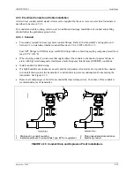
Installation
UMSITRPDS3-1
November
2010
4-16
10
0
100
700
600
200
1800
45
40
30
15
20
25
35
1700
1600
1500
1400
1300
1200
1100
1000
900
800
500
400
300
Loo
p R
esi
st
anc
e,
O
hm
s
Power Supply vs. Loop Resistance
Power Supply, Vdc
24
675
250
15.5
FIGURE 4-10 Power Supply vs. Loop Resistance
4.3.5.1 Point-to-Point Network
The graph in Section 4.3.5 defines an analog mode transmitter’s operating region for the allowable ranges
of supply voltage and network resistance. Perform the following calculations to ensure that the power
supply output voltage permits the transmitter to remain within the indicated operating range.
1.
Calculate the minimum power supply output voltage.
The minimum network power supply voltage requirement is a function of Network Resistance and
full scale current (20 mA), and is calculated by the following formula:
Minimum Power Supply Output Voltage = 10.5 volts + (0.02 × Network Resistance in ohms)
Power supply output voltage must be greater than the calculated value. The minimum voltage across
the input terminals of a transmitter is 10.5 volts.
2.
Calculate the maximum power supply output voltage.
The maximum network power supply voltage is a function of Network Resistance and zero scale
current (4 mA), and is calculated by the following formula:
Maximum Power Supply Output Voltage = V
max
+ (0.004 × Network Resistance in ohms)
Power supply output voltage must be less than the calculated value. The maximum voltage (
V
max
)
permitted across the input terminals is:
•
Non-intrinsically safe transmitter: 45 volts
•
Intrinsically safe transmitter: 30 volts
Содержание 7MF4033 series
Страница 48: ...Model 275 Universal Hart Communicator UMSITRPDS3 1 November 2010 2 26 ...
Страница 86: ...Installation UMSITRPDS3 1 November 2010 4 34 ...
Страница 152: ...Calibration and Maintenance UMSITRPSD3 1 November 2010 7 20 ...
Страница 158: ...Circuit Description UMSITRPDS3 1 November 2010 8 6 ...
Страница 197: ......
Страница 198: ......
Страница 200: ...Model Designations and Specifications UMSITRPDS3 1 November 2010 9 42 ...
Страница 204: ...Glossary UMSITRPDS3 1 November 2010 10 4 ...
Страница 208: ...Appendix A Online Configuration Map UMSITRPDS3 1 11 4 November 2010 ...
Страница 210: ...Appendix B Hazardous Area Installation UMSITRPDS3 1 12 2 November 2010 FIGURE 12 1 Control Drawing ...
Страница 211: ...UMSITRPDS3 1 Appendix B Hazardous Area Installation November 2010 12 3 FIGURE 12 2 Control Drawing ...
Страница 212: ...Appendix B Hazardous Area Installation UMSITRPDS3 1 12 4 November 2010 FIGURE 12 3 Control Drawing ...
Страница 216: ...Appendix C Elevation and Suppression Correction UMSITRPDS3 1 13 4 November 2010 ...

