Model Designations and Specifications
UMSITRPDS3-1
November
2010
9-28
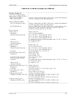
TABLE 9-11 Models 7MF4633 and 7MF4812, Specifications
Input
Measured variable
Level
Span (infinitely adjustable)
Span
Max. permissible test pressure
25 to 250 mbar g (0.36 to 3.63 psi g)
See Mounting Flange
25 to 600 mbar g (0.36 to 8.7 psi g)
See Mounting Flange
53 to 1600 mbar g (0.77 to 23.2 psi g)
See Mounting Flange
160 to 5000 mbar g (2.32 to 72.5 psi g)
See Mounting Flange
Lower measuring limit
• Measuring cell, silicone oil filling
-100% of span or 30 mbar (0.435 psi a), depending on mounting flange
Upper measuring limit
100% of maximum span
Output
Output signal
4 to 20 mA
• Lower limit (infinitely adjustable)
3.55 mA, factory preset to 3.84 mA
• Upper limit (infinitely adjustable)
23 mA, factory preset to 20.5 mA or optionally set to 22.0 mA
Load
• Without HART communication
R
B
≤
(U
H
– 10.5 V)/0.023 A; R
B
in
Ω
, U
H
: power supply in V
• With Hart communication
R
B
= 230 to 500
Ω
(SIMATIC PDM) or
R
B
= 230 to 1100
Ω
(HART Communicator)
Accuracy
To EN 60770-1
Reference Conditions
Increasing characteristic, start of scale value 0 bar, stainless steel seal diaphragm,
silicon oil filling, temperature 25°C (77°F) r: span ratio (r = max. span/set span)
Error in measurement and fixed-point
setting (including hysteresis and
repeatability)
• Linear characteristic
- r
≤
10
≤
0.15%
- 10 < r
≤
30
≤
0.3%
- 30 < r
≤
100
≤
(0.0075 * r + 0.075)%
Long-term drift (temperature change
+/-30°C (+/-54°F))
≤
(0.25 * r)% every 5 years
static pressure max. 70 bar g (1015 psi g)
Influence of ambient temperature
• at -10 to +60°C (14 to +140°F)
- 250 mbar (3.63 psi) measuring cell
≤
(0.5 * r + 0.2)%; 0.4 instead of 0.2 with 10 < r
≤
30)
- 600 mbar (8.7 psi) measuring cell
≤
(0.3 * r + 0.2)%; 0.4 instead of 0.2 with 10 < r
≤
30)
- 1600 and 5000 mbar (23.2 and 72.5
psi) measuring cell
≤
(0.25 * r + 0.2)%; 0.4 instead of 0.2 with 10 < r
≤
30)
• at -40 to -10°C and +60 to +85°C (-40
to +14°F and 140 to +185°F)
- 250 mbar (3.63 psi) measuring cell
≤
(0.25 * r + 0.15)%/10K; double values with 10 < r
≤
30)
- 600 mbar (8.7 psi) measuring cell
≤
(0.15 * r + 0.15)%/10K; double values with 10 < r
≤
30)
- 1600 and 5000 mbar (23.2 and 72.5
psi) measuring cell
≤
(0.12 * r + 0.15)%/10K; double values with 10 < r
≤
30)
Influence of static pressure
• on the zero point
- 250 mbar (3.63 psi) measuring cell
≤
(0.3 * r)% per normal pressure
- 600 mbar (8.7 psi) measuring cell
≤
(0.15 * r)% per normal pressure
- 1600 and 5000 mbar (23.2 and 72.5
psi) measuring cell
≤
(0.1 * r)% per normal pressure
• on the span
≤
(0.1 * r)% per normal pressure
Rated operating conditions
Degree of protection (to EN 60529)
IP65
Process temperature
Note:
Always take into account assignment of max. permissible working
temperature to max. permissible working pressure of the respective flange
connection!
Содержание 7MF4033 series
Страница 48: ...Model 275 Universal Hart Communicator UMSITRPDS3 1 November 2010 2 26 ...
Страница 86: ...Installation UMSITRPDS3 1 November 2010 4 34 ...
Страница 152: ...Calibration and Maintenance UMSITRPSD3 1 November 2010 7 20 ...
Страница 158: ...Circuit Description UMSITRPDS3 1 November 2010 8 6 ...
Страница 197: ......
Страница 198: ......
Страница 200: ...Model Designations and Specifications UMSITRPDS3 1 November 2010 9 42 ...
Страница 204: ...Glossary UMSITRPDS3 1 November 2010 10 4 ...
Страница 208: ...Appendix A Online Configuration Map UMSITRPDS3 1 11 4 November 2010 ...
Страница 210: ...Appendix B Hazardous Area Installation UMSITRPDS3 1 12 2 November 2010 FIGURE 12 1 Control Drawing ...
Страница 211: ...UMSITRPDS3 1 Appendix B Hazardous Area Installation November 2010 12 3 FIGURE 12 2 Control Drawing ...
Страница 212: ...Appendix B Hazardous Area Installation UMSITRPDS3 1 12 4 November 2010 FIGURE 12 3 Control Drawing ...
Страница 216: ...Appendix C Elevation and Suppression Correction UMSITRPDS3 1 13 4 November 2010 ...


