Model 275 Universal Hart Communicator
UMSITRPDS3-1
November
2010
2-8
2.4 GETTING TO KNOW THE COMMUNICATOR
The HART Communicator operates either on-line or off-line. Off-line operation is used to create or edit a
configuration that can then be downloaded to a HART device, such as a transmitter. On-line operation is
used to download a configuration to a HART device, upload a configuration, edit HART device operating
parameters, and monitor process values.
For off-line operation, the Communicator need not be connected to a HART device. On-line operation
requires a connection to a powered HART device.
The menu that appears first when the Communicator is turned on depends on whether the Communicator
is connected to a powered HART device.
•
Communicator not connected - Main menu (off-line operation)
•
Communicator connected - Online menu (on-line operation)
To work off-line when connected to a powered loop, access the Main menu from the Online menu by
pressing the LEFT ARROW/PREVIOUS MENU key.
Note
Communicator internal operation is controlled by firmware. Consequently,
operation will depend upon the firmware version and the installed device drivers,
as discussed in this section.
2.4.1 Display Icons
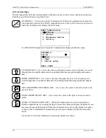
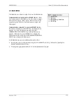
Several different symbols (icons) appear on the LCD to show the state of the Communicator and provide
visible response to actions of the user. Figure 2-3 shows the display icons and how they relate to keypad
functions.
Low Battery
HART Communication
( indicates connected
device is configured in
the burst mode)
Access Additional
Menu Items
Access
Previous
Menu
HART Communicator
Device Info
6 Write Protect Yes
X
03
034S
1
2 Dev Type
3 Dev ID 0
4 Tag
5 MM/DD/YY 10/10/10
FIGURE 2-3 HART Communicator Display Icons
Содержание 7MF4033 series
Страница 48: ...Model 275 Universal Hart Communicator UMSITRPDS3 1 November 2010 2 26 ...
Страница 86: ...Installation UMSITRPDS3 1 November 2010 4 34 ...
Страница 152: ...Calibration and Maintenance UMSITRPSD3 1 November 2010 7 20 ...
Страница 158: ...Circuit Description UMSITRPDS3 1 November 2010 8 6 ...
Страница 197: ......
Страница 198: ......
Страница 200: ...Model Designations and Specifications UMSITRPDS3 1 November 2010 9 42 ...
Страница 204: ...Glossary UMSITRPDS3 1 November 2010 10 4 ...
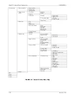
Страница 208: ...Appendix A Online Configuration Map UMSITRPDS3 1 11 4 November 2010 ...
Страница 210: ...Appendix B Hazardous Area Installation UMSITRPDS3 1 12 2 November 2010 FIGURE 12 1 Control Drawing ...
Страница 211: ...UMSITRPDS3 1 Appendix B Hazardous Area Installation November 2010 12 3 FIGURE 12 2 Control Drawing ...
Страница 212: ...Appendix B Hazardous Area Installation UMSITRPDS3 1 12 4 November 2010 FIGURE 12 3 Control Drawing ...
Страница 216: ...Appendix C Elevation and Suppression Correction UMSITRPDS3 1 13 4 November 2010 ...


