UMSITRPDS3-1
Installation
November 2010
4-31
4.6 ELECTRICAL INSTALLATION
This section describes loop wiring for Point-to-Point and Multi-Drop networks. Refer also to Section 4.8
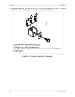
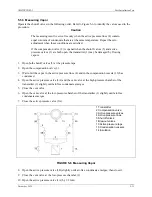
for installation in hazardous locations. Figure 4-17 shows typical conductor terminations.
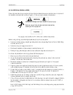
WARNING
Hazardous voltage can cause death or serious injury.
Remove power from all wires and terminals before
working on this equipment.
CAUTION
Use supply wires suitable for 5°C (10°F) above ambient temperature.
Before wiring the loop, the following should already have been completed:
•
Selection of either analog or digital operating mode and corresponding Point-to-Point or Multi-Drop
network; Section 4.3.4.
•
Selection of a power supply; Section 4.3.5.
•
Mechanical installation of transmitter(s) installed; Section 4.4.
•
Pulling of loop cable through conduit and into terminal compartment; Section 4.5.3.
To connect the transmitter to the loop, perform the following steps.
1.
Remove power from all involved wires and terminals.
2.
Access the transmitter signal terminals by removing the enclosure cap nearest to the electrical
entrance. Turn the cap counterclockwise.
3.
Determine method of connection to transmitter signal terminals; see Figure 4-17 for typical
connection methods.
4.
Strip loop cable and conductors. Install ring tongue or spring spade terminals for #8 screws and the
cable conductor gauge. If terminals will not be used, tin conductor ends and form a loop.
5.
Connect the loop cable to the LOOP (+) and (-) terminals inside the transmitter’s enclosure. Refer to
Figures 4-6 through 4-9 for the needed connections for the type of network. Terminals will
accommodate wire sizes up to 16 AWG (1.3 mm
2
).
6.
Install the enclosure cap by turning it clockwise until the O-ring contacts the enclosure, Tighten the
cap one additional turn to compress the O-ring.
7.
If one of the two electrical conduit entrances in the housing is not used, it should be plugged. Refer to
the transmitter’s rating plate and Section 9 to determine whether entrance holes accept 1/2-NPT or
M20 x 1.5 fittings.
Seal 1/2-NPT fitting with Teflon tape; seal M20 fitting with a soft setting sealing compound rated for
at least 105ºC (221ºF).
Содержание 7MF4033 series
Страница 48: ...Model 275 Universal Hart Communicator UMSITRPDS3 1 November 2010 2 26 ...
Страница 86: ...Installation UMSITRPDS3 1 November 2010 4 34 ...
Страница 152: ...Calibration and Maintenance UMSITRPSD3 1 November 2010 7 20 ...
Страница 158: ...Circuit Description UMSITRPDS3 1 November 2010 8 6 ...
Страница 197: ......
Страница 198: ......
Страница 200: ...Model Designations and Specifications UMSITRPDS3 1 November 2010 9 42 ...
Страница 204: ...Glossary UMSITRPDS3 1 November 2010 10 4 ...
Страница 208: ...Appendix A Online Configuration Map UMSITRPDS3 1 11 4 November 2010 ...
Страница 210: ...Appendix B Hazardous Area Installation UMSITRPDS3 1 12 2 November 2010 FIGURE 12 1 Control Drawing ...
Страница 211: ...UMSITRPDS3 1 Appendix B Hazardous Area Installation November 2010 12 3 FIGURE 12 2 Control Drawing ...
Страница 212: ...Appendix B Hazardous Area Installation UMSITRPDS3 1 12 4 November 2010 FIGURE 12 3 Control Drawing ...
Страница 216: ...Appendix C Elevation and Suppression Correction UMSITRPDS3 1 13 4 November 2010 ...


