On-Line Operation
UMSITRPDS3-1
November
2010
6-12
6.2.5 Zero Adjustment (Position Correction)
The zero error resulting from a non-vertical installation position can be easily corrected. This procedure
can be performed locally using the magnetic pushbuttons or remotely using the HART Communicator.
Section 7 Calibration and Maintenance discusses the cause of this zero error.
IMPORTANT
To zero an absolute pressure transmitter, a vacuum must be applied! The zero
adjustment of a ventilated absolute pressure transmitter will cause an erroneous
zero set.
1.
Ventilate or evacuate the transmitter.
•
Ventilate for pressure, differential pressure, flow, and flanged level transmitters.
•
Evacuate for absolute transmitters to <0.1% of the measuring span.
2.
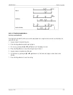
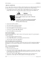
Select mode 7 by pressing the mode pushbutton.
3.
Set zero by simultaneously pressing the
(
and
'
pushbuttons for 2 seconds; 0.000 will appear in the
display.
4.
Press the M pushbutton until no mode number is shown. An output current of 4 mA is generated.
6.2.5.1 Zero-Point Alignment at Absolute Pressure
Performing a position correction to an absolute pressure transmitters may not properly calibrate zero if a
vacuum is not available as the reference pressure. In this case, the three options below are available.
•
Perform a lower sensor alignment using the Communicator.
Carry out a lower sensor alignment at an applied, known and sufficiently stable reference pressure.
With this type of alignment, the digital displayed measured value is adjusted. The output current is
relative to this displayed value.
•
Set the current in mode 2 of local operation.
Use the formula below to calculate the current to be set for a known, sufficiently stable reference
pressure. (See the footnote below.)
mA
mA
p
p
p
p
I
zo
fso
setpt
ref
4
16
)
(
)
(
+
∗
−
−
=
In model 2, enter this current with the
(
and
'
pushbuttons and save the value by pressing the M
pushbutton.
With this setting, the digital displayed value is not changed.
•
Change the value of the start of measurement in mode 5 of local operation:
2
If the applied process pressure is known and sufficiently stable, it can be used instead of the reference pressure.
Enter mode 4, when necessary, and enter an appropriate damping value.
Содержание 7MF4033 series
Страница 48: ...Model 275 Universal Hart Communicator UMSITRPDS3 1 November 2010 2 26 ...
Страница 86: ...Installation UMSITRPDS3 1 November 2010 4 34 ...
Страница 152: ...Calibration and Maintenance UMSITRPSD3 1 November 2010 7 20 ...
Страница 158: ...Circuit Description UMSITRPDS3 1 November 2010 8 6 ...
Страница 197: ......
Страница 198: ......
Страница 200: ...Model Designations and Specifications UMSITRPDS3 1 November 2010 9 42 ...
Страница 204: ...Glossary UMSITRPDS3 1 November 2010 10 4 ...
Страница 208: ...Appendix A Online Configuration Map UMSITRPDS3 1 11 4 November 2010 ...
Страница 210: ...Appendix B Hazardous Area Installation UMSITRPDS3 1 12 2 November 2010 FIGURE 12 1 Control Drawing ...
Страница 211: ...UMSITRPDS3 1 Appendix B Hazardous Area Installation November 2010 12 3 FIGURE 12 2 Control Drawing ...
Страница 212: ...Appendix B Hazardous Area Installation UMSITRPDS3 1 12 4 November 2010 FIGURE 12 3 Control Drawing ...
Страница 216: ...Appendix C Elevation and Suppression Correction UMSITRPDS3 1 13 4 November 2010 ...


