On-Line Operation
UMSITRPDS3-1
November
2010
6-20
6.4 REMOTE CONFIGURATION AND OPERATION BY HART
This section describes operation of the transmitter using the Model 275 HART Communicator.
Alternatively, PC software such as SIMATIC PDM can be used. Refer to the operating instructions or on-
line help provided with the software. Refer to Section 2 for details concerning use of the Communicator.
Appendix A has the complete On-Line Configuration Map (an on-line Map for the Model 375 Field
Communicator is at the back of this manual). Refer to the map as necessary to navigate the menus. The
HART command set is constantly being enhanced and the specific commands available with the HART
Communicator at hand may be different from those described here.
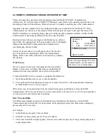
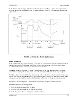
Most procedures in this section begin at the Online menu, which is
shown here. The pulsing heart in the upper right corner of the display
indicates that the HART Communicator and transmitter are
communicating with each other.
In most of the procedures, text will appear above the function
keys. These keys are immediately below the Communicator
display. Refer to the table in Section 2 for function key (softkey)
descriptions.
Write Protect
If an L is present in the lower left quadrant of the transmitter’s
display, write protect is enabled. Operating or configuring the
transmitter from a remote HART device will not be possible.
To allow the HART device to operate or configure the transmitter:
1.
Open the pushbutton access cover on the transmitter.
2.
Press and hold the M pushbutton for at least 5 seconds. The letter L will extinguish and commands
from the HART device will be accepted.
Write protect can be enabled either from the transmitter magnetic pushbuttons or from the HART
Communicator. There are several levels of write protect. Refer to Section 6.2.8 or 6.4.9 for an explanation
of write protect levels and methods of enabling.
6.4.1 Process Data
The Online menu displays pressure and transmitter type information. By pressing 3 on the HART
Communicator keyboard, the Device Setup menu can be displayed and several other screens displaying
process data can be accessed.
For example:
1.
In the Online menu, press 3 Device Setup.
2.
In the Device Setup menu, press 1 Process Variables.
3.
The Process Variables display appears. It shows active data for pressure, % range, analog output, and
sensor temperature.
SITRANS P:
♥
Online
"!
1 Pres
0.004 inH2O
2 Type
Diff PN160
3
#
Device setup
HELP | SAVE
Note: If using a Model 375 Field
Communicator, see the inside of
the front cover of this manual.
Содержание 7MF4033 series
Страница 48: ...Model 275 Universal Hart Communicator UMSITRPDS3 1 November 2010 2 26 ...
Страница 86: ...Installation UMSITRPDS3 1 November 2010 4 34 ...
Страница 152: ...Calibration and Maintenance UMSITRPSD3 1 November 2010 7 20 ...
Страница 158: ...Circuit Description UMSITRPDS3 1 November 2010 8 6 ...
Страница 197: ......
Страница 198: ......
Страница 200: ...Model Designations and Specifications UMSITRPDS3 1 November 2010 9 42 ...
Страница 204: ...Glossary UMSITRPDS3 1 November 2010 10 4 ...
Страница 208: ...Appendix A Online Configuration Map UMSITRPDS3 1 11 4 November 2010 ...
Страница 210: ...Appendix B Hazardous Area Installation UMSITRPDS3 1 12 2 November 2010 FIGURE 12 1 Control Drawing ...
Страница 211: ...UMSITRPDS3 1 Appendix B Hazardous Area Installation November 2010 12 3 FIGURE 12 2 Control Drawing ...
Страница 212: ...Appendix B Hazardous Area Installation UMSITRPDS3 1 12 4 November 2010 FIGURE 12 3 Control Drawing ...
Страница 216: ...Appendix C Elevation and Suppression Correction UMSITRPDS3 1 13 4 November 2010 ...


