Calibration and Maintenance
UMSITRPSD3-1
November
2010
7-12
7.4.2 Replacing the Electronics Module
A larger tweezers (4"-6") is very useful in the procedure below.
Removal
1.
Fasten an anti-static wrist strap on your wrist and connect its ground lead to the transmitter
enclosure ground screw.
2.
If present, remove the display as described in the previous section.
3.
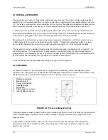
Refer to Figure 7-2 and remove the two hex standoffs (7) using a 3/32" (2.5 mm) hex wrench. Grasp
the pull tab (6) and withdraw the electronics module (3) from the enclosure. As shown in Figure 7-3,
the measuring cell cable (4) is several inches long. Fold the module down so the back of the assembly
is visible, as shown.
IMPORTANT
Do not allow the electronics module to hang on the measuring cell cable. The
measuring cell board and the cable are part of the measuring cell assembly.
Damaging the board or cable will require replacement of the entire measuring
cell.
4.
On the back of the electronics module, locate the measuring cell board (2) and the measuring cell
cable (4). The measuring cell board plugs into the electronics module and two flexible clips (3) secure
the board. Grasp the board by inserting tweezers between the clips and the board. Slightly rock the
board while applying outward pressure to ease the connectors apart.
5.
Set the electronics module aside in an anti-static bag.
MG
00353a
5
6
4
3
2
1
1
2
3
4
5
6
Electronics Module, rear view; module shown pulled
out of transmitter enclosure and folded down
Measuring cell board
Flexible clips securing measuring cell board, qty 2
Measuring cell cable, loop between feed-thru pins
Feed-thru pins, qty 2, in transmitter enclosure
Feed-thru pin receptacles, qty 2
FIGURE 7-3 Electronics Module Removal and Installation
Содержание 7MF4033 series
Страница 48: ...Model 275 Universal Hart Communicator UMSITRPDS3 1 November 2010 2 26 ...
Страница 86: ...Installation UMSITRPDS3 1 November 2010 4 34 ...
Страница 152: ...Calibration and Maintenance UMSITRPSD3 1 November 2010 7 20 ...
Страница 158: ...Circuit Description UMSITRPDS3 1 November 2010 8 6 ...
Страница 197: ......
Страница 198: ......
Страница 200: ...Model Designations and Specifications UMSITRPDS3 1 November 2010 9 42 ...
Страница 204: ...Glossary UMSITRPDS3 1 November 2010 10 4 ...
Страница 208: ...Appendix A Online Configuration Map UMSITRPDS3 1 11 4 November 2010 ...
Страница 210: ...Appendix B Hazardous Area Installation UMSITRPDS3 1 12 2 November 2010 FIGURE 12 1 Control Drawing ...
Страница 211: ...UMSITRPDS3 1 Appendix B Hazardous Area Installation November 2010 12 3 FIGURE 12 2 Control Drawing ...
Страница 212: ...Appendix B Hazardous Area Installation UMSITRPDS3 1 12 4 November 2010 FIGURE 12 3 Control Drawing ...
Страница 216: ...Appendix C Elevation and Suppression Correction UMSITRPDS3 1 13 4 November 2010 ...


