Installation
UMSITRPDS3-1
November
2010
4-6
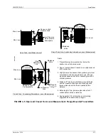
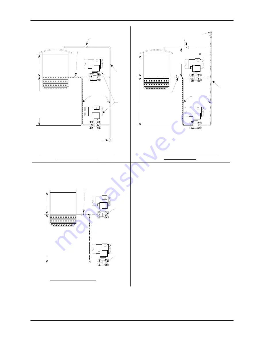
A. Pressurized (Closed) Vessel Installation:
Non-Condensable Fluid
B. Pressurized (Closed) Vessel Installation:
Condensable Fluid
C. Open Vessel Installation
MG
00
346b
Max. Range
Min. Range
LP Shut-Off
Valve
HP Shut-Off
Valve
LP
HP
Note 3
Note 1
Dripleg and Drain Valve
LP line
empty -
not filled
with con-
densate.
Suppressed-Zero: To
calculate maximum
distance, subtract
actual span setting
from range limit given
in specification.
Notes:
1. Transmitter may be mounted at or below the
minimum level to be measured.
2. Open or vented vessels require only a high pressure
(HP) connection.
3. High pressure line senses static pressure plus level.
Low pressure line senses pressure only. The two
pressures oppose each other, canceling the effect
of static pressure.
4. Distance "X" can be any distance since both high
and low pressure lines have equal and opposite
forces which cancel the forces created by this
distance.
5. Entire length of low pressure pipe is kept full of
condensate to act as a reference.
6. See Appendix C for information on calculating
suppressed and elevated zero ranges.
Max. Range
Min. Range
HP Shut-Off
Valve
LP
HP
Vent
Span
Suppressed-Zero: To
calculate maximum
distance, subtract
actual span setting
from range limit given
in specification.
Vent
Span
Fill Connection
See
Section 9
Specifi-
cations
for range
limit.
LP line
filled with
condensate
Max. Range
Min. Range
LP Shut-Off
Valve
HP Shut-Off
Valve
LP
HP
Note 3
Span
Distance X
See Note 4
Elevated-Zero,
Distance Y,
Note 5
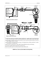
FIGURE 4-2 Differential Liquid Measurement Piping
Содержание 7MF4033 series
Страница 48: ...Model 275 Universal Hart Communicator UMSITRPDS3 1 November 2010 2 26 ...
Страница 86: ...Installation UMSITRPDS3 1 November 2010 4 34 ...
Страница 152: ...Calibration and Maintenance UMSITRPSD3 1 November 2010 7 20 ...
Страница 158: ...Circuit Description UMSITRPDS3 1 November 2010 8 6 ...
Страница 197: ......
Страница 198: ......
Страница 200: ...Model Designations and Specifications UMSITRPDS3 1 November 2010 9 42 ...
Страница 204: ...Glossary UMSITRPDS3 1 November 2010 10 4 ...
Страница 208: ...Appendix A Online Configuration Map UMSITRPDS3 1 11 4 November 2010 ...
Страница 210: ...Appendix B Hazardous Area Installation UMSITRPDS3 1 12 2 November 2010 FIGURE 12 1 Control Drawing ...
Страница 211: ...UMSITRPDS3 1 Appendix B Hazardous Area Installation November 2010 12 3 FIGURE 12 2 Control Drawing ...
Страница 212: ...Appendix B Hazardous Area Installation UMSITRPDS3 1 12 4 November 2010 FIGURE 12 3 Control Drawing ...
Страница 216: ...Appendix C Elevation and Suppression Correction UMSITRPDS3 1 13 4 November 2010 ...

