Installation
UMSITRPDS3-1
November
2010
4-10
4.3.4 Transmitter Operating Mode and Network Type
A transmitter outputs either an analog current or an equivalent digital signal, depending upon the selected
operating mode. The operating mode also determines the type of network (Point-to-Point or Multi-Drop)
to be installed, as shown in Table 4-1 and the following subsections.
TABLE 4-1 Operating Mode and Network
OPERATING MODE
NETWORK TYPE
NETWORK FIGURE(S)
Analog
Point-to-Point
4-6, 4-7, and 4-8
Digital Multi-Drop
4-9
4.3.4.1 Analog Mode
When a transmitter is configured for analog mode operation, the following statements apply.
•
The transmitter outputs a 4-20 mA signal for input to devices such as controllers and recorders.
•
A Point-to-Point network is used comprising a transmitter, Primary/Secondary Master, and other non-
signaling devices. The transmitter polling address is 0 (zero).
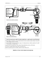
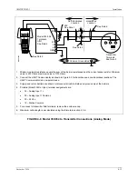
Point-to-Point networks are shown in Figures 4-6, 4-7, and 4-8.
•
The optional display can be used for local indication of transmitter output.
•
Each transmitter is factory configured for analog mode unless otherwise ordered. The polling address
is set to zero (0).
•
A Model 275 HART Communicator is used for configuration, diagnostics, and reporting the current
process variable.
Note: If using a Model 375 Field Communicator, see the inside of the front
cover of this manual.
Содержание 7MF4033 series
Страница 48: ...Model 275 Universal Hart Communicator UMSITRPDS3 1 November 2010 2 26 ...
Страница 86: ...Installation UMSITRPDS3 1 November 2010 4 34 ...
Страница 152: ...Calibration and Maintenance UMSITRPSD3 1 November 2010 7 20 ...
Страница 158: ...Circuit Description UMSITRPDS3 1 November 2010 8 6 ...
Страница 197: ......
Страница 198: ......
Страница 200: ...Model Designations and Specifications UMSITRPDS3 1 November 2010 9 42 ...
Страница 204: ...Glossary UMSITRPDS3 1 November 2010 10 4 ...
Страница 208: ...Appendix A Online Configuration Map UMSITRPDS3 1 11 4 November 2010 ...
Страница 210: ...Appendix B Hazardous Area Installation UMSITRPDS3 1 12 2 November 2010 FIGURE 12 1 Control Drawing ...
Страница 211: ...UMSITRPDS3 1 Appendix B Hazardous Area Installation November 2010 12 3 FIGURE 12 2 Control Drawing ...
Страница 212: ...Appendix B Hazardous Area Installation UMSITRPDS3 1 12 4 November 2010 FIGURE 12 3 Control Drawing ...
Страница 216: ...Appendix C Elevation and Suppression Correction UMSITRPDS3 1 13 4 November 2010 ...


